Arduino Bluetooth IR Remote Controller Project
Infra-Red (IR) Protocols Explanation
IR Protocols Introduction
I will discuss in this page about implemented protocols, starting from an overview and then focusing on each protocol to explain their specs and operating mode.
In general, an IR Protocol is a set of rules that specifies how to transmit a group of bits or bytes. There is a device, the transmitter, which send those pulses thanks to an IR Led that blinks at a specific frequency for a certain amount of time and then turns off for another amount of time. Each bit, 0 or 1, is encoded with a specific combination of these timings and so it is possible for the receiver to distinguish them.
As we have said before, there are three important protocols and now I'm going to explain each one features.
NEC Protocol
NEC is maybe the best known one and the most widespread. It has been developed by NEC and adopted by many companies (perhaps it’s royalty-free, but I didn’t find anything certain about this). Its waveform is made of a start frame, a bit stream and a final terminator.
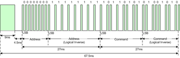
The start frame is a PWM burst 9ms long, equivalent to 16 times the base timing T of 562.5us. In this phase the IR Led blinks and then it follows a pause of 4.5ms.
Now the bitstream begins. Four bytes are transmitted. Only two of them contain the proper data, the address of the receiver and the command, and they are interleaved with their logical inverse bytes (bitwise not). This is like an error check implementation. All the information bits are streamed LSB first.
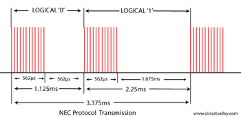
A logical 1 consists of a 562.5us (1x T) pulse burst followed by a pause of 1687.5us (3x T), for a total duration of 2250us (4x T).
A logical 0 consists of a 562.5us (1x T) pulse burst followed by a pause of another 562.5us (1x T), for a total duration of 1125us (2x T).
Since the bitstream contains also the logical inverse bytes, its total duration is constant and lasts 67.5ms plus the terminator which is just another standard pulse of 1x T.
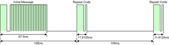
It is stated that two consecutive streams must be separated by a total time of 108ms from start edge to start edge.
There is also a dedicated code that means “repeat last command”. It is made by a 9ms start burst followed by 2.25ms of pause and a standard pulse of 1x T.
Each 562.5us pulse is realized with PWM technique with a suggested duty cycle of 1/4 or 1/3. The carrier frequency is set at 38KHz.
SONY SIRC Protocol
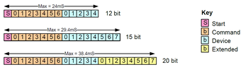
SIRC is a proprietary protocol by SONY and there exist three variants, with 12, 15 or 20 bits. Command field is length-fixed with 7 bits in all the three versions. All the information bits are streamed LSB first.
Its carrier frequency is set at 40KHz and even in this case there is not a fixed PWM duty cycle.
It is similar to the NEC protocol because there is a start frame and bit logical value 1 or 0 is distinguished by the pulse duration and not the pause like the previous one.
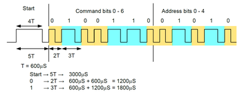
The start frame is 3ms long, equivalent to 4 times the base timing T of 600us and then a pause of 1x T follows.
A logical 1 consists of a 1200us (2x T) pulse burst followed by a pause of 600us (1x T), for a total duration of 1800us (3x T).
A logical 0 consists of a 1x T pulse burst followed by a pause of another 1x T, for a total duration of 1200us (2x T).
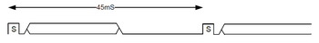
In this case the total stream duration is unknown because it depends on the value of transmitted bits but each stream is padded with a pause such as the total duration before the following frame start edge lasts 45ms.
A single command consists of 3 repeated streams and unlike the NEC protocol there isn’t a dedicated repeat code but it’s encoded just repeating the entire command stream as long as the user releases the button.
PHILIPS RC5 & RC6 Protocol
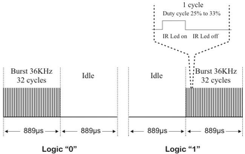
RC5 and RC6 are two different protocols by Philips, both based on the Manchester coding. Their carrier frequency is set at 36KHz with a recommended PWM duty cycle of 1/4 or 1/3 but, again, it’s not mandatory.
In the Manchester coding the bit time is provided by a constant clock, so both the values 1 and 0 take the same amount of time but in one case the pulse precedes the pause (here this is a logical 0), in the other is the opposite (here this is a logical 1).
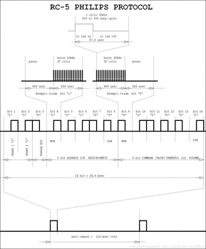
Let’s start with RC5. Its stream has four fields: a start frame, a toggle bit, the address field and the command field. Unlike previous protocols, all these fields are simple bits, even the start frame, so they are all based on the fundamental time interval T of 889us. Every bit takes two of that time interval for a total duration of 1778us.
The start frame is always a sequence of two logical 1 followed by a toggle bit. This bit has the role of “repeat” identifier. If two consecutive streams have the same toggle bit, it means that the user is holding the button pressed. If the toggle bit value changes, then the user has pressed a button twice. It changes value on every new release-and-press.
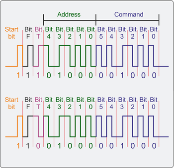
For completeness, I must say that there is also an Extended version of RC5 protocol, in which the second start bit is used as 7th command bit. In this case, its value can be either 0 or 1 and the decoded value (as 7th bit) is the inverse, so if it is 0 then it is decoded as 1 queued to the other command bits (it will be the LSB bit).
The bitstream is divided in address (5 bits) and command (6 bits), transmitted MSB first. Like in the NEC case, the total duration of a stream is fixed to 24.892ms, due to the equal bit timing. Two streams are divided, start edge to start edge, by 114ms
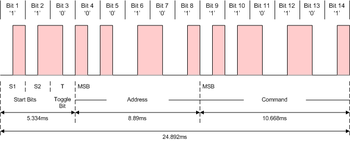
RC6 is similar and different at the same time. It’s based on Manchester coding too but there is a "proper" start frame, unlike RC5 protocol, the toggle bit duration is twice the normal bit one and logical values 0 and 1 are encoded in the opposite way than they are in RC5. The carrier frequency remains fixed at 36KHz.
The start frame is 2.666ms long followed by a pause of 889us and a logical 1, for a total duration of 3.556ms + 889us, equivalent to 10x T, considering T the base timing of 889/2us. Then, 3 logical 0 and the toggle bit follow the start frame. The toggle bit has twice the duration of a common bit, so it takes 1.778ms (4x T). It works exactly the same as in the RC5 protocol.
Now there are the address and command fields, both constituted of one byte of data, transmitted MSB first.
The total stream duration takes 23.114ms to complete and between two consecutive streams there is an interval (start edge to start edge) of 106.27ms.
Some websites report an interval T of 895us instead of 889us. Since the difference of just 6us isn’t relevant, I decided to keep the second as the right one, which is the same value used also in the RC5 version. Even with an oscilloscope it has been difficult to understand which was the correct one. I don’t have any Philips device for testing my assumption, so I can’t say it’s 100% correct and working.
Fujitsu AC Protocol
The last protocol analyzed is used by a Fujitsu air conditioner. It’s the most experimental one because there was almost any documentation about it, as I mentioned at the beginning.
The analysis has been possible thanks to the function implemented in Arduino that uses the board like a very basic and rudimental oscilloscope and prints the waveform on the monitor in real time.
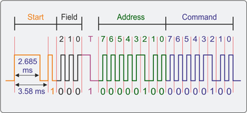
The carrier frequency is set at 38KHz with a basic time interval T of approximately 420us, 16 cycles of the carrier frequency.
The start frame consists of 128us (8x T) followed by a pause of 64us (4x T ). Logical 1 consists of a pulse of length T followed by a pause of the same length, while a logical 0 has a pause of 2x T . Then there is a tail which is just a pulse of length T.
As you can see, the stream encoding rules are very similar to NEC protocol ones, where logical 1 and 0 are distinguished by the pause duration.
The stream has a variable length in terms of number of bits, depending on the number of information to be transmitted: for example, the power-on command carries also informations about the desired temperature and wings position (while power off doesn’t) so it’s longer than other commands. However, every command is a multiple of 8 bits, a byte.
This protocol is implemented as well in Arduino, of course it’s not guaranteed it works with every air conditioner, neither every Fujitsu device, since I have tested it only on my own one.
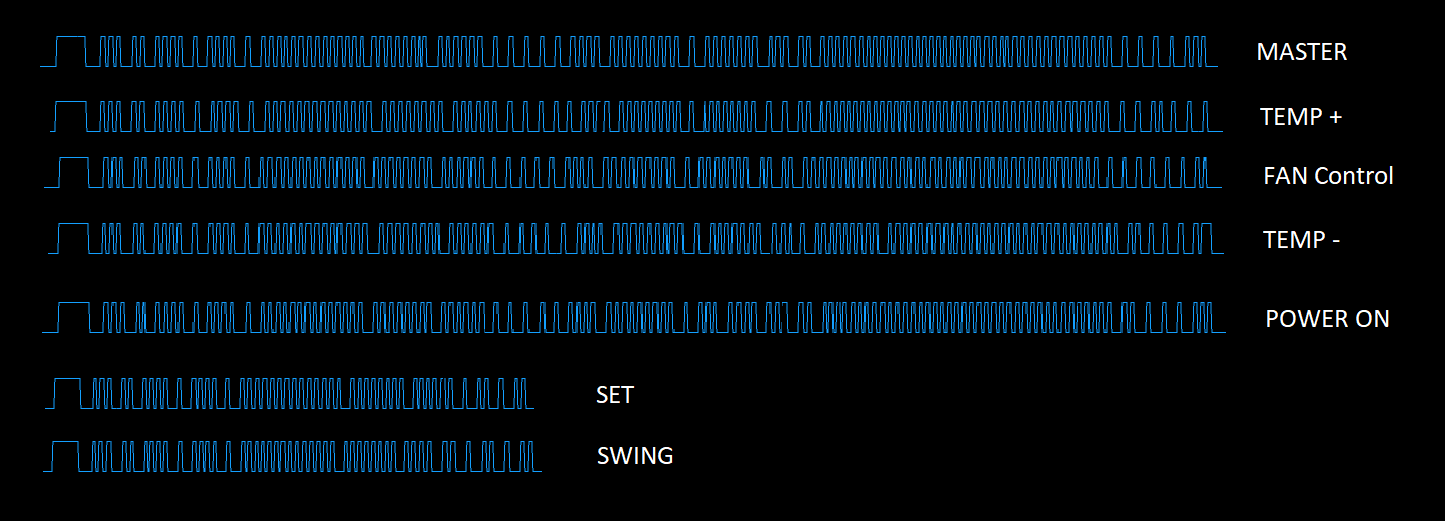
Some decoded values are:
    SET:
    0x28C6000808 36

    SWING:
    0x28C6000808 B6

    TEMPERATURE: (27-26-25 °C)
    0x28C6000808 3F 100C0D4 000000000 78
    0x28C6000808 3F 100C054 000000000 74
    0x28C6000808 3F 100C094 000000000 7C

    MASTER (Here it is in 'Fan' mode):
    0x28C6000808 3F 100C05C 000000000 B4
I intentionally added a space where values differ to highlight differences.
As you can see, they have different lenght and some bytes are always the same, like the first 5 bytes which could maybe represent the device address.