Arduino Bluetooth IR Remote Controller Project
Arduino Development
Arduino Introduction
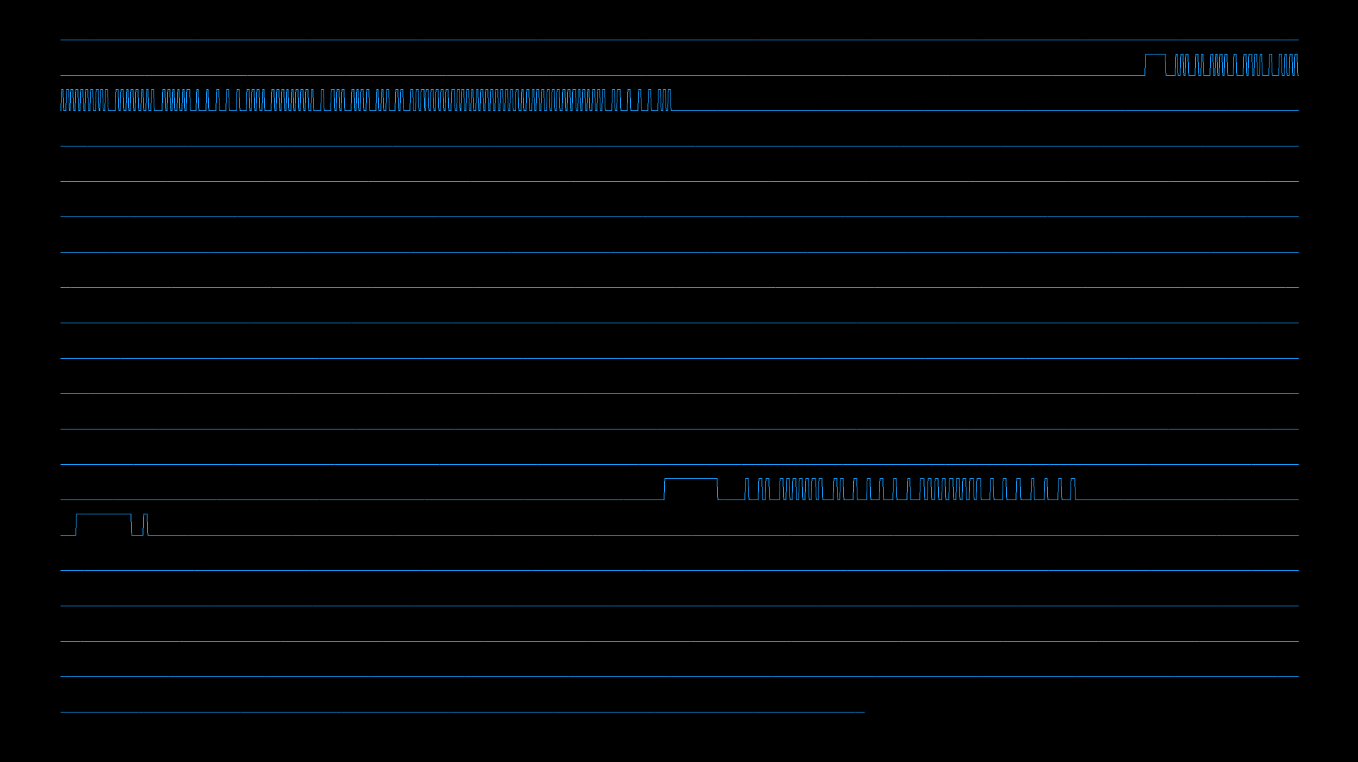
Let’s start with the main part of this project, the development of a receiver and transmitter with and Arduino M0 board. When I started this project I didn’t know anything about IR protocols and how they work, so I thought to code a simple oscilloscope function to see some waveforms as a first step. The sketch in Arduino is very easy and consists of a loop of 4 seconds where a digital pin with a photodiode connected is being red repeatedly and plotted on screen thanks to a little program written with Processing.
This is the Arduino code used for this purprose:
    //read input from pin IN_IR and print on serial port
    void Leo_IR_Read::readAndDisplaySerial () {

        fine = micros() + 4000000; // 4 seconds
        while (micros() <= fine) {
            x = digitalRead (IN_IR);
            mySerialPort.println(x);
        }
    }
The result is something like this:
At the beginning an analog pin was used but due to the high read time requested by the analogRead() function, about 208us, I switched to digital pin and digitalRead() function which takes about 1us for a reading. Moreover, the output signal of TSOP2238 is intrinsically digital, so if we use this one instead of the photodiode, digitalRead() function is certainly a better choice. In this case, the output rate is limited by Arduino serial communication rate, which takes hundreds of us for each transmission, even at the maximum baud rate of 115200bps, decreasing the effective reachable resolution.
Due to this high latency, it’s impossible to detect the PWM oscillation at the carrier frequency with Arduino. Maybe it would be using an array stored in the main memory, but in this case only few thousands of values can be stored (so, if a digitalRead() takes 1us, just few milliseconds would be recorded) and then sent through the serial port. But in this case, with this “burst” technique, there would be a lack of time between two consecutive bursts due to the time needed by the serial communication.
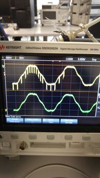
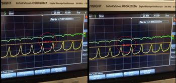
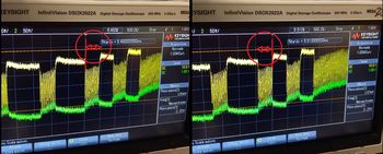
So, the carrier frequency check has been done only in a second moment using a digital oscilloscope in the laboratory of the university.
Code Development: Decoding
Now let’s analyze more deeply the code written to implement a receiver which must be able to automatically recognize and decode a protocol between those implemented.
The code is organized in classes:
- Arduino sketch – just to setup and ask the user what to do.
- Receiver module class.
- Transmitter module class.
- A class for each protocol - with useful function for both decoding and transmitting.
- A couple of extra files for setup the Arduino timer and serial port.
The protocol recognition is based on the start frame duration, which is different for each one of them, and is performed by a function of the receiver class. Then the proper protocol object is used to perform the decoding phase. Decoding functions are different from protocol to protocol, either for simplicity and for didactic finalities.
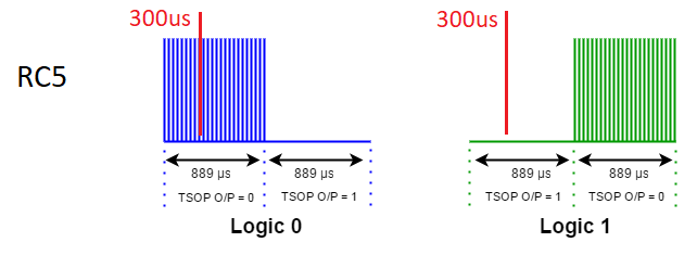
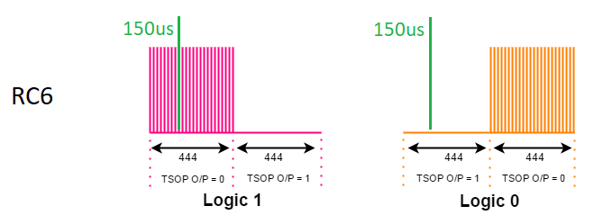
For example, to decode the Philips protocol, which is based on a Manchester coding, an input pin is red at a regular interval equal to the bit-time but shifted inside the first half part of this period. Depending on the value, a 0 or 1 is decoded.
For NEC and Sony protocols it’s possible to discriminate a logical 1 from a logical 0 looking at the duration of the pause (for NEC) or the pulse (Sony). In these cases, an edge sensitive function has been used to calculate the time interval of interest.
Code Development: Transmitting
This first part has been developed quite easily, without strange bugs or difficulties.
Some more problems have been found in the transmitter part of the project, with many revisions needed to work properly. The first implementation used the delayMicroseconds() function to simulate the PWM behavior of the carrier signal, turning on and off the digital output pin (set it HIGH or LOW).
    //nec send logical 1
    void Leo_IR_Nec::send1_PWM() {
       //ir led on
       long pwmtime;
       while (micros() < (int)(my_time + NEC_PULSE_my_time*(cT + 1) - upTimePWM)) {   //-upTimePWM as margin for not exceeding 562.5us pulse time
          pwmtime = micros();
          digitalWrite(OUT_IR, HIGH);
          delayMicroseconds(7);
          digitalWrite(OUT_IR, LOW);
          delayMicroseconds(19);
       }
       //ir led off
       digitalWrite(OUT_IR, LOW);
       while (micros() < (int)(my_time + NEC_PULSE_my_time*cT + NEC_ONE_my_time))
       {} // wait
       cT += 4;
    }
A variant to this first approach uses a while() cycle, in which the output pin had to stay HIGH or LOW for a certain amount of time based on the chosen duty cycle.
    //nec send logical 1
    void Leo_IR_Nec::send1_PWM() {
       //ir led on
       long pwmtime;
       while (micros() < (int)(my_time + NEC_PULSE_my_time*(cT + 1) - upTimePWM)) {   //-upTimePWM as margin for not exceeding 562.5us pulse time
          pwmtime = micros();
          digitalWrite(OUT_IR, HIGH);
          while(micros() < pwmtime + upTimePWM){};
          digitalWrite(OUT_IR, LOW);
          while(micros() < pwmtime + upTimePWM + downTimePWM){};
       }
       //ir led off
       digitalWrite(OUT_IR, LOW);
       while (micros() < (int)(my_time + NEC_PULSE_my_time*cT + NEC_ONE_my_time))
       {} // wait
       cT += 4;
    }
These strategies worked well with two devices I have at home, both using NEC protocol. Unfortunately, in a subsequent test with a Sony TV it didn’t work in any way, even changing a little the timings used to reproduce the desired duty cycle.
This led to other tests and internet researches until I found some websites that suggested using Arduino built in timers for a more precise PWM wave shape. In fact delayMicroseconds() function has a poor precision of some us, which is ok for the bitrate but it’s too poor for an accurate PWM modulation of a signal at 40KHz and similar.
At this point I decided to use timers of Arduino, so I had to search some tutorial and study the proper chapters - 30 and 31 - of the Atmel sam-d21 datasheet. This has been the most challenging part of the hardware project because there are very few examples of code for my M0 board. Most of them are coded for Arduino Uno, which uses different register names and a different configuration. Moreover, it was my first time programming a microcontroller going so deeply and setting his hardware registers, not really a user-friendly operation for someone at the beginning. Even the Atmel datasheet is not very useful at a first read, because there aren’t code examples that explain how to implement what is written and sometimes there aren’t neither all the keyword and register names you can use to program it.
Most of the keywords or functions I used in my timer class don’t exist in the entire datasheet (performing a CTRL+F, no matches are found).
Fortunately, I finally found a useful tutorial that I used as a base for my proposals, changing it a little to fit my project and to stabilize it, because at the typical frequencies used in this project, that code sometimes failed, freezing the program execution.

In my timer implementation, I used the MFRQ wavegen option and Timer Counter Compare Channels (TC CC) 0 and 1 as mark points for interrupts handling to reproduce a PWM behaviour.
Max is the maximum value the counter can reach, in this case a 16 bit timer can reach the value of 216-1, increasing by one at each clock cycle. CC0 register has the top value which is computed to match the desired frequency, CC1 register has the value that matches the desired Duty Cycle - for example, for a duty cycle of 50%, CC1 is equal to CC0/2.
This is the main part of Timer class:
    //timer useful functions

    TC = (TcCount16*) TC3;
    void Leo_IR_Timer::initTimer(int freqHz, int dutyC){

       REG_GCLK_CLKCTRL = (uint16_t) (GCLK_CLKCTRL_CLKEN | GCLK_CLKCTRL_GEN_GCLK0 | GCLK_CLKCTRL_ID (GCM_TCC2_TC3)) ;
       while ( GCLK->STATUS.bit.SYNCBUSY == 1 );
       TC->CTRLA.reg &= ~TC_CTRLA_ENABLE;
       // Use the 16-bit timer
       TC->CTRLA.reg |= TC_CTRLA_MODE_COUNT16;
       while (TC->STATUS.bit.SYNCBUSY == 1);
       // Use match mode so that the timer counter resets when the count matches the compare register
       TC->CTRLA.reg |= TC_CTRLA_WAVEGEN_MFRQ;
       while (TC->STATUS.bit.SYNCBUSY == 1);
       // Set prescaler to 1
       TC->CTRLA.reg |= TC_CTRLA_PRESCALER_DIV1;
       while (TC->STATUS.bit.SYNCBUSY == 1);
       setTimerFreqAndDuty(freqHz, dutyC);
       // Enable the compare interrupt on CC0 for TOP value, CC1 for PWM Duty Cycle
       TC->INTENSET.reg = 0;
       TC->INTENSET.bit.MC0 = 1;
       TC->INTENSET.bit.MC1 = 1;
       NVIC_EnableIRQ(TC3_IRQn);
       enableTimer();
    }
    void Leo_IR_Timer::enablePWM(){
       NVIC_EnableIRQ(TC3_IRQn);
    }
    void Leo_IR_Timer::disablePWM(){
       NVIC_DisableIRQ(TC3_IRQn);
       digitalWrite(pinOut,LOW);
    }
    void Leo_IR_Timer::enableTimer(){
       TC->CTRLA.reg |= TC_CTRLA_ENABLE;
       while (TC->STATUS.bit.SYNCBUSY == 1);
    }
    void Leo_IR_Timer::disableTimer(){
       NVIC_DisableIRQ(TC3_IRQn);
       delay(1);
       TC->CTRLA.reg &= ~TC_CTRLA_ENABLE;
       while (TC->STATUS.bit.SYNCBUSY == 1);
    }

    //duty cycle: int from 0 to 100
    void Leo_IR_Timer::setTimerFreqAndDuty(int freq, int duty){
       int compareValue = (CPU_HZ / (TIMER_PRESCALER_DIV * freq)) - 1;
       // Make sure the count is in a proportional position to where it was
       // to prevent any jitter or disconnect when changing the compare value.
       TC->COUNT.reg = map(TC->COUNT.reg, 0, TC->CC[0].reg, 0, compareValue);
       TC->CC[0].reg = compareValue;
       TC->CC[1].reg = compareValue*duty/100; //duty cycle
       while (TC->STATUS.bit.SYNCBUSY == 1);
    }
    //interrupt handling function
     void TC3_Handler(){
       // If this interrupt is due to the compare register 0 matching the timer count
       // we toggle the LED on.
       if (TC->INTFLAG.bit.MC0 == 1) {
          TC->INTFLAG.bit.MC0 = 1;
          digitalWrite(tc3_outPin, HIGH);
       }
       // If this interrupt is due to the compare register 1 matching the timer count
       // we toggle the LED off, pwm duty cycle is over.
       else if (TC->INTFLAG.bit.MC1 == 1) {
          TC->INTFLAG.bit.MC1 = 1;
          digitalWrite(tc3_outPin, LOW);
       }
       else {
          //"reset"
          TC->INTFLAG.bit.MC0 = 1;
          TC->INTFLAG.bit.MC1 = 1;
          TC->INTFLAG.bit.SYNCRDY = 1;
          TC->INTFLAG.bit.ERR = 1;
          TC->INTFLAG.bit.OVF = 1;
       };
    }
Finally, a new test on the Sony TV with this improvement led to the desired behavior, recognizing correctly all the transmitted commands. Maybe this TV has a more sensitive hardware/software and requires a “cleaner” waveform to work as expected.
Here a piece of code as example:
    //Sony send logical 1 with Timer


    void Leo_IR_Sony::send1_Precise_PWM() {

       //ir Led on
       myTimer->enablePWM();
       while (micros() < (my_time + SONY_PULSE_my_time*(cT + 2))) {}

       //ir Led off
       myTimer->disablePWM();
       while (micros() < (my_time + SONY_PULSE_my_time*cT + SONY_ONE_my_time)) {}

       cT += 3;
    }
Code Development: Bluetooth
Now that the core part works fine, the last step is to add the HC-05 module, such that you can use Arduino even in wireless mode with a laptop, smartphone or anything else thanks to the Bluetooth connection. This is necessary also for the next Android app development.
Fortunately this upgrade has been quite easy to setup, it just needed the change of the input/output serial port and a little configuration of the HC-05. Only the configuration has been a little tricky because my module didn’t enter in the full-admin mode. I followed the instructions found online but there was no way to made it work, so I used the partial-admin mode which is good enough for change the baud rate from default value of 9600bps to 115200bps for a faster communication speed.
At this point a new strange problem arose: NEC protocol stopped working, even if something was still transmitted (IR Leds blinked). This only happens using Bluetooth. There is a file, mySerial.hpp, where a preprocessor directive specifies if SerialUSB or Serial5 has to be used, defining the variable mySerialPort as SerialUSB or Serial5 depending if you want to use USB or Bluetooth. If USB is selected, everything works fine, but with Serial5 (Bluetooth) I had to remove some prints from the NEC function codificaDatoDaTrasmettere() to makes it work. Fujitsu and Sony work well in both cases. I didn’t understood the reason of this very strange behavior but it’s solved moving away some lines of code.
    //nec encode data for transmission

    void Leo_IR_Nec::codificaDatoDaTrasmettere(String& s) {

       ...

       //print encoded data
       mySerialPort.print("\nValori codificati (stampati nell'ordine in cui saranno inviati): ");
       int valToPrint = valueIR;
       for (int i = 0; i < 32; i++) {
          mySerialPort.print(((valToPrint >> i) & 1));
       }
       mySerialPort.println("");
    }


// I had to remove the lines above or NEC stopped working if mySerialPort == Serial5
// These lines are still there in all other protocols, working well... only NEC gives trouble...
This concludes the hardware part with Arduino. C++ classes should be modular enough for a future improvement if you want to add other protocols not yet implemented.
Code Development: Final Notes
Just a couple of things:
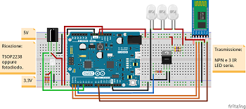
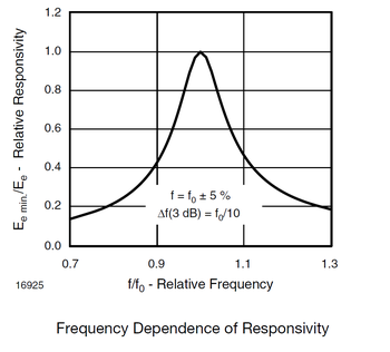
- There are different versions of TSOP device and their I/O pin position aren’t the same in all of them! TSOP2238 has the following configuration: 1 = OUT 2 = Vdd 3 = GND. I chose this model because its center frequency is 38KHz, so its sensibility is good enough even for frequency of 36 or 40 KHz.

- I used these components just because I had them at home (resistors and bjt). With this configuration, you should have approximately 1mA base current on the bjt and 20mA collector current. I tested them with a digital multimeter and I found a base current of 0.8mA and a collector current of 13mA (17x). For a better result, you should have a lower collector load resistance to reduce voltage drop which should be now at the limit of the forward region of the bjt (Vc ~ Vb --> Vcb ~ 0, so it's not optimal) and maybe use another bjt in cascade (Darlington pair) for a brighter light emission - and so a wider operating distance.
- Arduino M0 default serial port is not Serial as in Arduino Uno but it is SerialUSB. All its pins work at 3.3V with a maximum current of 7mA.
-
Most of Arduino source file comments are in ITALIAN because when I started the project it wasn't supposed to be in english and when I knew it, I had already written a lot of comments. Translating all of them in English would have been very time-expensive. I decided to remove them from the english version, I translated just some of them.
Sorry...
