Hardware development
This phase of the project describes the hardware interconnection and the rationale behind the choices made for each component.
- Video Acquisition. Video acquisition is executed by means of an ordinary commercial webcam, having sufficient image quality to obtain a good trade-off between resolution and CPU processing time.
- Mobile Stand. Movement is obtained employing two servos, one for horizontal and one for vertical movement, mounted on a specific stand that allows the device to be fixed and the webcam to move smoothly.
- Image processing. Image processing, that is the main bulk of the workload, is executed by a software with graphic interface which runs on a laptop with a Linux distribution.
- Servo control. Handling of the servos is carried out with the aid of the Arduino board, specifically projected for allowing an easy interface with the program running on the computer and subsequent trasmission of command signals to the servos. The board also handles the drive of the LEDs on the stand.
- LED. LEDs are present to notify the occurrence of pre-defined events.
- Green LED: Device is on and working.
- Yellow LED: A servo has reached its limit. It entails possible coerced conclusion of the tracking.
- Red LED: Can be on only along with the two other LEDs. It indicates that the servos have been brought back to their default position. Whilst the red LED is on, the Arduino board cannot receive new messages from the software.
Used components
The following table shows the components utilized for the realization of the prototype.
| Component | Immage | Description - Link |
|---|---|---|
WebCam |
 |
RB-See-295 |
| 2x Servos |  |
SG90Servo |
| Stand |  |
Pan/Tilt bracket for servos |
| Arduino |  |
Arduino Due |
| 3x LED diodes | 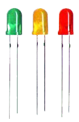 |
Available at the laboratory |
| 3x Resistors | 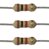 |
Available at the laboratory |
Interconnections and circuits
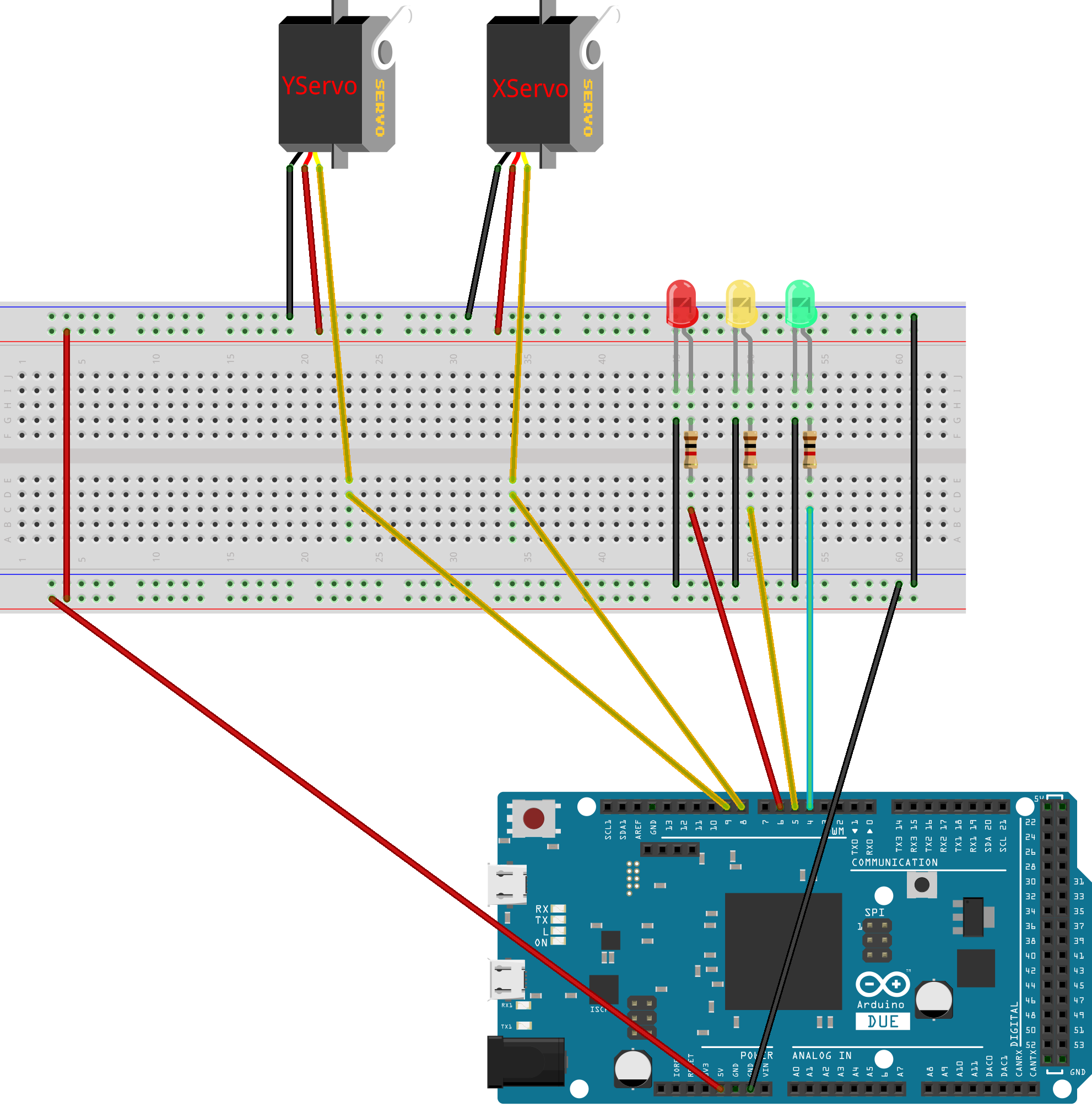
The laptop is connected to the Arduino board through a micro-B USB cable on Arduino Due "programming port". The webcam is connected to the laptop trhough a common USB cable. The connection of the LED diodes requires a printed drive circuit; everything is powered by the laptop.
For the realization of the prototype a Breadboard has been used. The circuit implemented consists only of a resistor/LED series to limit the current to each diode.
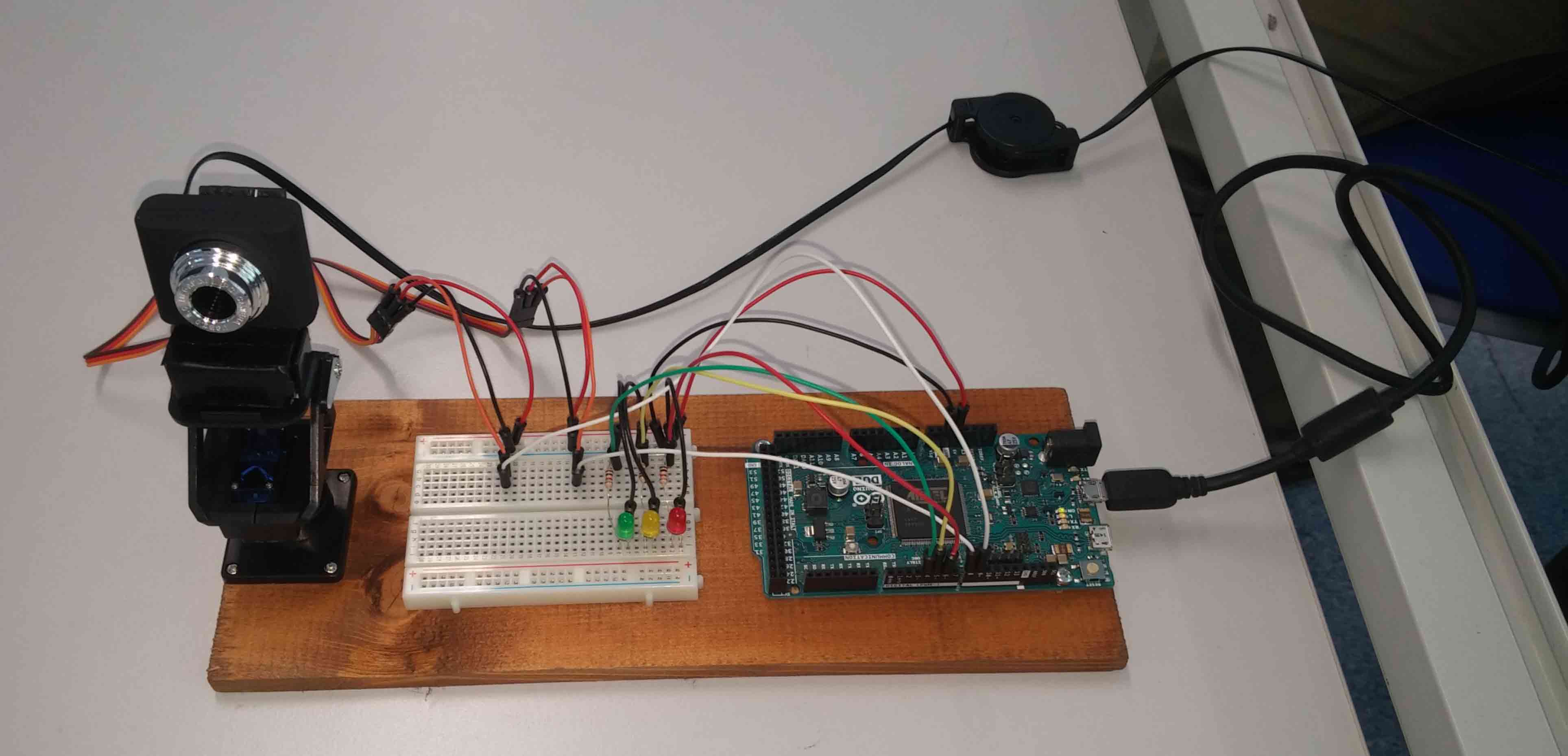
Final prototype
Finally, all the components were interconnected. The following image shows the final result: