
The initial scheme for the realization of a virtual piano was the one shown in figure and contemplated the presence of a transmitter and two receivers.
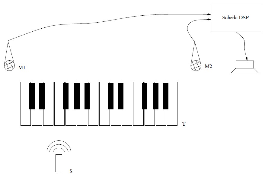
The user would have moved, along the dummy keyboard T, a source S emitting sounds (or ultrasounds) which would have been received by the two microphones M1 and M2 and sent to the DSP. By comparing the phase of the signals read by M1 and M2, the DSP would have determined the position of the source S along T and produced a note of the desired frequency.
We immediately realized that the sound emitted by the source S should be at an inaudible frequency, or low enough to be not detectable, for not to compromise the listening to the note generated by the DSP.
We initially planned to use infrasounds, or anyway frequencies low enough to be difficoult to hear. We chose a tone at 30 Hz,
intending to estimate the path difference between the sound
waves received by microphone M1 and those received by microphone M2 from the phase difference between the two signals.
Such a procedure, since the wavelength of a sound signal at 30 Hz is more than 10 meters, allows to estimate without ambiguity
path differences up to that length: this is more than enough for a keyboard of the usual dimensions.
So, first of all we have written a Matlab script to simulate processing.
This script performs the following operations:
- stereo data are acquired via computer microphone: left and right channels are loaded into two different columns of a matrix of samples
- initial low-pass filtering and decimation are performed
- a selective filtering is performed to isolate the signal at 30 Hz
- to calculate the phase shift phi2-phi1, the two samples from the two microphones are multiplied: because of Werner formulas, A1*sin(2*pi*30*t+phi1)*A2*sin(2*pi*30*t+phi2)= 0.5*A1*A2*(cos(phi2-phi1) - cos(4*pi*30*t+phi1+phi2))
- at this point there are two components, one at zero frequency, the other at 60 Hz; to keep only the DC component, 0.5*A1*A2*cos(phi2-phi1), we eliminate the 60 Hz component thanks to a notch filter and then with a low-pass filter we eliminate any noise at higher frequencies
- to get the cosine only, we divide by 0.5*A1*A2: to do this, we need to estimate the two signal amplitudes, by taking the square and isolating the DC component with the same filters applied to the product
- arccosine provides phi2-phi1, which is precisely the phase difference
- the time delay can be obtained as (phase difference)/(2*π*frequency), in our case frequency is 30 Hz
- the path difference is equal to the time delay multiplied by the speed of sound; in the script the speed of sound is considered constant, but an initial calibration might have been added to take account of its dependence on various factors, such as temperature and air humidity
- the distance of emitter S from the beginning of the keyboard can be calculated from the path difference with simple trigonometric calculation.
If pairs of sine waves generated by Matlab and arbitrarily shifted are provided as input, the script works perfectly and the phase shift is estimated with great precision. Problems arise however when you are going to build the system phisically: to emit a 30 Hz signal with a power sufficient to be detected and processed, a large loudspeaker is needed and it certainly cannot be approximated as a point source... The resulting keyboard would have been too long.
We were therefore constrained to change our strategy. The alternative chances were two: to use an audible frequency (some kHz) or ultrasounds. The first strategy was already used by another working group. According to some advice we had received, using ultrasound capsules would have been the best thing to do - and above all it would have been easy (sic).
So we decided to choose the second strategy...