The whole system has been implemented as a telecommunication system.
Given an audio file (audio_orig) and a web URL, the first thing to do is to embed the latter in the first. The main idea is to code the text to bits and use a digital modulation to get an audio signal that has to be added to audio_orig. This has to be done only once for a specific media: the resulting audio file (audio_out) can then be played in any device with proper speakers. This part will be referred later as URL TO AUDIO.
While the modified audio is being played, a device with a proper microphone has to record it and recover the URL from it. Here things are to be done in the reversed order: the recorded audio signal has to be demodulated to get the bits that are decoded to the text. This part will be referred later as AUDIO TO URL.
It's worth noting that there is no need that the text to embed is a web URL; however, as explained later, the text encoding has been optimized for those.
Audio Files Format
The system has been simplified by using audio files with the following characteristics:
| Format | WAV |
| Compression | none |
| Sampling rate | 44100 Hz |
| Number of channels | 2 (stereo) |
| Bit depth | 16 bit |
The reasons of this is that 44100 Hz/16 bit is a standard. Also, no compression has been considered, as this can damage or even remove the modulated signal.
The reason for using two channels is that many audio systems have two speakers, the left and the right one, and the same is true for many audio tracks. The system still works if the output stereo sound is played in a mono system; however, this is not guaranteed if more speakers are involved (no test have been done, though).
On the contrary, the recording is supposed to be a mono sound, as many devices have only one microphone.
Frequencies Constraints
As the modification to the original audio should be inaudible and, on average, humans can hear only sounds up to 20 kHz (although most adults cannot hear sound even above 17 kHz), a good choice would be to use a modulated signal in the ultrasound frequencies, that are above 20 kHz.
However, many commercial devices don't operate well on these (there's no need as humans cannot hear them) and were not designed to transmit a modulated message: the speakers or the microphone may distort those frequencies and may not be able to work with a sampling rate higher than standard FS=44100 Hz, so this is the one that will be used. As a consequence of Shannon's theorem, given this sampling rate, it's possible to use frequencies up to 22050 Hz.
Furthermore, mainly because of non idealities and internal filters, the frequency response of the devices may not be flat below and near 20 kHz, too.
That's why frequencies in the range 17.5-19 kHz have been used, as they are still inaudible to most people (children and animals may still hear the embedded sound as a whistle, though).
To keep the band limited, BPSK modulation has been used, with squared-root raised cosine pulse shape. Tests were also made with QPSK, but symbols were not that much distinguishable and decoding failed: this is not described here (there are only few elements that differs), but in the source code it still possible to select it.
Also, a burst transmission is done, based on what is described here and here).
Also, a small bitrate BPS has been used; in particular, it was chosen one that was a divisor of FS, so that there is an integer number of samples for each bit (NS) and as a consequence sampling is simplified in the demodulation. The values that have been used are:
BPS = 525 bit/sec NS = FS / BPS = 84 samples/bitFurthermore, a carrier of frequency FC will be used. This is chosen so that is a multiple of the bitrate, so that there is an integer number of periods for each bit:
FC = BPS · k = 18375 HzThe modulated messages that encode the URL are inserted more than once in the original audio: if the decoding of a burst fails, another attempt can be made soon, so it can take advantage of temporal diversity. Also, the messages that encode the URL are inserted interleaved in two the original audio channels: as sounds will have different paths, spatial diversity can be exploited, too.
Non Idealities of the System
The whole system is highly non ideal and there are several causes of noise and interference to it:
- The original audio itself, as it's noise to the embedded modulated signal; because of this happens only in the band effectively used by the modulation, and these should be inaudible frequencies, to solve this, the original audio can be filtered with a stopband filter.
- The speakers, as their response may be distorted in the used frequencies and their components generate noise; this varies depending on the device used.
- The recorder, as its response may be distorted in the used frequencies and its components generate noise; this varies depending on the device used.
- The environment, both because of external noise and of interference caused by reflections, echoes and reverberation.
- The user, because of movements that causes Doppler effect. Furthermore, the position and distance from the speakers and the direction of the output sounds are to be considered, as the attenuation and the reflected waves, that are recorded too, have different impact.
Doppler effect has a greater impact with sound waves compared to radio waves. The velocity of sound depends on the mean in which it propagates and other characteristics, mostly by temperature. On average it is c = 343 m/s on air. The speakers are supposed to be stationary, while the recording devices may be moving (in the direction of the source) at a velocity of v , in the order of cm/s, because of the user that holds it. The frequencies will be shifted by:
Δf = ± f · v / cIn the following table are reported estimated carrier frequency shifts (using FC) for some realistic values of v. Despite small, they have effect on the demodulation (the shifts are also time variant). On the contrary, the bitrate is not affected that much, as is smaller.
| v [cm/s] | |ΔFC| [Hz] |
|---|---|
| 0.05 | 2.68 |
| 0.1 | 5.36 |
| 0.2 | 10.71 |
| 0.5 | 26.76 |
Coding text to bits
As the system is highly non ideal, there is some high probability of error during transmission in certain situations, so, even if BPSK modulation provide some good immunities to noise, channel coding is needed. However, that means that there is much overhead due to the bits added to detect or correct errors. That's why it's important to code the text so that the smaller number of bits represents it.
Instead of coding text with the ASCII code of each character, a custom variation of Varicodes have been used to do so: these are entropic variable-length codes, so the most frequent symbols are encoded with a smaller number of bits. A custom RLE encoding can be done in the resulted bit sequence, too.
Data have to be valid to be converted back to text: a single error bit means a different character is decoded, and the resulting URL may be invalid or may point to a different website. So, CRC codes have been calculated and added to the end of bit-encoded message.
Then, the result is protected by convolutional codes and Reed-Solomon codes (useful for detection and correction of burst errors). This is a common concatenated scheme found in many communication systems and increases a lot the probability of recovering the right text even in presence of errors.
Also, to address Doppler effect, the resulting bits have been differentially encoded, so in fact DBPSK is used as modulation. Also, a consequence of this choice is that to demodulate the signal, it is not necessary to recover the phase of the carrier accurately.
Working Conditions
Despite all of this, the developed system can handle few situations; to have better results its required that:
- The user must be as close as possible to the speakers to avoid great attenuation and reflections.
- The user must keep the recorder as still as possible to avoid the Doppler effect.
- The speakers' volume must be quite high to mitigate noise. However, depending on the used device, a very high volume may produce distortion on the message because of saturation: as a consequence, audible frequency components are produced and so the inserted messages will become audible, too; also, speakers may be damaged.
- The quality of the speakers and microphone must be as high as possible to have the less distortion and additive noise on the signal.
As described in Testing, some test were performed in different situations: sometimes, in good conditions (mainly when the channel distortion is low), no error are produced at all , so channel coding would not be needed. In other cases, there are some errors that are all corrected. In other situations (mainly when the channel distorts the signal too much), too much errors are produced and the URL cannot be recovered.
The Whole System
The complete scheme used for implementing the URL TO AUDIO is the following:
 URL TO AUDIO encoding, modulation and embedding scheme. Blue boxes represent the message domain, the green ones the modulated signal domain and the violet ones the audio domain.
The scheme used for implementing for the AUDIO TO URL is the following:
 AUDIO TO URL demodulation and decoding scheme. Blue boxes represent the message domain and the green ones the modulated signal domain
A detailed description is being given in the following sections.
From URL to AUDIO
Message Domain: Varicodes encoding
The system should work for every kind of text, however, as the main application is to transmit an URL, the coding of the text (text_orig) into the bit array m_var has been optimized for that.
Coding the first part of the URL
Given the URL to embed , in most of the cases there are few possible structures for the first part of it. Instead of coding each letter of these with its 7-bit ASCII code (extended characters are not considered), a 3-bit coding has been used:
| First part | Coding | N° of bits (using 7-bit ASCII coding) |
Compression ratio (in respect to 7-bit ASCII coding) |
Example of URL |
|---|---|---|---|---|
| "http://" | 000 | 49 | 16.33/1 | http://example.com |
| "https://" | 001 | 56 | 18.67/1 | https://example.com |
| "http://www." | 010 | 77 | 25.67/1 | http://www.example.com |
| "https://www." | 011 | 84 | 28/1 | https://www.example.com |
| "www." | 100 | 28 | 9.33/1 | www.example.com |
| other | 101 | 0 | 3 bit added | example.com |
Despite the 3 bits added in the "other" case, which is not that much, in all other cases (which are very frequent) there is a big reduction in terms of number of bits in respect to the 7-bit ASCII coding.
The remaining part of the URL
For the remaining part of the URL, custom Varicodes have been used.
Varicodes are entropic codes that map each character to a variable-length bit sequence that starts and ends with a 1 and has at most one consecutive 0. The more frequent a character is, the smaller number of bits is used. Codes are built in the following way: starting from code 1 (the shortest), the others can be obtained by prepending a 1 or a 10 to it, then to the obtained codes, etc., so the first codes are: 1, 11, 101, 1011, 1101, 1111,10101 and so on. Also, between different characters a space sequence is inserted (00): this makes the decoding easier.
More information can be found here.
For original Varicodes, mapping is based on the frequencies of characters in the English texts; in this context, supposing that the data to transmit are web URLs, as the frequencies of character in these is different, a new mapping is used.
First of all, only a subset of characters is needed. As reported in RFC 3986, the only ones valid for an URL and that have been considered are reported in the following table:
| Unreserved characters | A B C D E F G H I J K L M N O P Q R S T U V W X Y Z a b c d e f g h i j k l m n o p q r s t u v w x y z 0 1 2 3 4 5 6 7 8 9 - . _ ~ |
| Reserved characters | : / ? # [ ] @ ! $ & ' ( ) * + , ; = |
| Percent encoded | % |
Also, as in web URLs there may be some special string patterns, the following have been considered and mapped to a single code:
| Extensions | ".html", ".htm", ".asp", ".aspx", ".jsp", ".cgi", ".shtml", ".pdf" |
| Top level domains | ".com", ".org", ".net", ".us", ".gov", ".edu", ".it", ".uk", ".co.uk", ".ac.uk", ".de", ".fr", ".es" |
| Language indicators | "/en/", "/en-us/", "/en-gb/", "/it/", "/it-it/", "/fr/", "/fr-fr/", "/de/", "/de-de/", "/es/", "/es-es/", "en.", "en-us.", "en-gb.", "it.", "it-it.", "fr.", "fr-fr.", "de.", "de-de.", "es.", "es-es." |
| Some popular websites (from here) | "google.com", "youtube.com", "facebook.com", "wikipedia.org", "amazon.com", "twitter.com", "instagram.com", "google.de", "google.co.uk", "linkedin.com", "google.fr", "t.co", "imgur.com", "google.it", "ebay.com", "bing.com", "tumblr.com", "blogspot.com", "imdb.com", "pinterest.com", "amazon.de", "amazon.co.uk", "wikia.com", "bbc.com", "bbc.co.uk", "bit.ly", "tinyurl.com", "t.co", "youtu.be" |
| Other | "index", "media", "info", "watch" |
To assign a Varicode to each pattern a frequency analysis has been performed. First of all, a list of web URLs has been extracted from the Website Classification Dataset UK - Selective Web Archive (DOI: 10.5259/ukwa.ds.1/classification/1). Then, the C++ program FrequencyCalculator has been written to count the frequencies of each character or pattern reported in the tables above. Substrings or characters are not considered if they are part of a bigger pattern (e.g. when wikipedia.org is found, only the counter of wikipedia.org is incremented, not those of .org, w, i, k, ...). Also, the initial part of the URLs (http://, https://, ...) is not considered, as it's coded on its own. Then the patterns are ordered by frequency (more frequent first); if this is the same, they are ordered by length (shorter first) and if again this is the same by alphabetical order. The results are saved in a file. Lastly, the C++ program VaricodeGenerator has been written to read that file and assign a Varicode to each of the already ordered patterns (the first ones have shorter codes).
These programs and the resulting mapping can be found and downloaded in the Sources page.
As there is a maximum size of the message signal to transmit, there is also a maximum size of the coded text. It's not possible to define the maximum number of characters that an URL can have, as a variable length encoding is used. However, it is enough to code most URLs. If this is not the case, an URL shortener service like tinyurl or bitly can be used.
There is a good compression ratio in respect to using ASCII codes (on average it is of 1.5-2), however, if many non-frequent patterns are used, it could also be worse. Another specific dataset or method can be used to perform the frequency analysis to construct a new proper mapping. Also, it's easy to adapt the system to be able to embed a generic text (e.g. by using only the original Varicodes). In both cases, the modifications must be consistent with the relative ones in the AUDIO TO URL part.
Example
Given the following URL:
text_orig = https://example.com/index.htmlit will be coded as:
| https:// | e | x | a | m | p | l | e | .com | / | index | .html | ||||||||||||
| 001 | 1 | 00 | 11010111 | 00 | 101 | 0 0 | 11111 | 0 0 | 110101 | 0 0 | 11011 | 0 0 | 1 | 0 0 | 1101101 | 0 0 | 11 | 0 0 | 11111111 | 0 0 | 11111101 | 0 0 | 00 |
The length of this is 81 bits. If 7-bit ASCII code were used, 217 bits would have been needed (there are 30 characters plus one terminating code).
Message Domain: RLE encoding
Given the structure of the Varicode encoded message m_var, it is possible to compress it a little further, producing the bit array m_rle. Of course, the first PRE_LEN bits are just coded as they are, because they have a different encoding. For the others, a variation of binary RLE compression can be used. This works by coding the positive alternating runlengths of 0 and 1. In this implementation, different codings have been used for the two, with the first one considered always referred to the run of ones (because the first bit is always referred to a codeword and its encoding always starts by 1).
As the maximum runlength of zeros is two by construction (except the ending bit pattern), the two possible bit sequence of zeros can be coded using one bit only.
| Runlength of 0 | Encoding |
| 0 | 0 |
| 0 0 | 1 |
Instead, the sequence of consecutive ones can have different runlengths depending of the Varicode dictionary and the text to encode. Also, shorter runlength are more probable. So, to encode these, unary coding have been used.
| Runlength of 1 | Encoding |
| 1 | 1 |
| 1 1 | 0 1 |
| 1 1 1 | 0 0 1 |
| 1 1 1 1 | 0 0 0 1 |
| 1 1 1 1 1 | 0 0 0 0 1 |
| 1 1 1 ... 1 1 | 0 0 0 ... 0 1 |
Lastly, the encoding of the ending pattern (0000) is the encoding of the first two zeros, that is 1, followed by 00. As shown later, this way it can be decoded correctly (briefly: as a runlength of 1 is expected after the decoding of the first two zeros and the expected encoding is 00...001, if no ending 1 bit is found, it will be decoded as another 00). Also, this does not change if more zeros are appended to m_rle.
 Custom RLE encoding (the first PRE_LEN bits are not coded).
Of course, as only the runlength of two zeros is compressed, this does not provide a good compression: is only about 12%. However, this could be enough to avoid obtaining more bits in the following step.
Message Domain: Zero Padding
The next step should be calculating and appending the CRC (which length is CRC_N) to m_rle, obtaining the bit array m_crc; as the following step is doing the Reed-Solomon encoding, and this is done in blocks of RS_K·RS_S bits, it is necessary that the length of m_crc is a multiple of that number to have full codewords. As this is not always the case, sometimes it is necessary to append zeros to m_rle to obtain the bit array m_rle_zp. This has to be done before appending the CRC, because the receiver has to know where this is, and he does not know how many zero bits have been added.
 The bit message has to be zero padded to have full Reed-Solomon codewords (after appending the CRC).
The number of zeros to append is:
RS_K · RS_S − mod(length(m_rle) + CRC_N, RS_K · RS_S)Message Domain: CRC calculation
As anticipated before, now the CRC of size CRC_N has to be calculated for m_rle_zp and appended to it, creating the bit array m_crc, so that if there are some errors they are detected.
To do so, the bit sequence has to be seen as a polynomial: every bit represents a coefficient. For example:
[1 0 1 1] ⇔ x3 + x + 1The polynomial m_rle_zp has to be multiplied by xCRC_N. Then, the CRC is simply the reminder of the polynomial division, modulo two, between that result and another special polynomial, called generator, of grade CRC_N. To implement the calculation, some optimization can be done, though.
The choice of CRC_N and the generator polynomial determines how many errors can be detected. For this data bit array the standard CRC-16-CITT (CRC_N=16) polynomial has been used:
x16 + x12 + x5 + 1More details can be found here and here.
Message domain: Reed-Solomon encoding
Now m_crc has to be protected by error correcting codes. Firstly, Reed-Solomon codes are used and m_rs is obtained. These are block codes useful to detect and correct burst errors: to do this, the message is divided into data symbols of size RS_S bits and every block of RS_K symbols, parity symbols are appended to form a new block of RS_N symbols (data + parity). As it is a systematic code, the message is not altered. RS_N is chosen so that:
RS_N ≤ 2^RS_S - 1Also, there are RS_N-RS_K parity symbols, and the number RS_T of symbol errors that can be corrected is:
RS_T = (RS_N-RS_K)/2 when RS_N-RS_K is even RS_T = (RS_N-RS_K-1)/2 when RS_N-RS_K is odd The bit message is divided into blocks of RS_K symbols of RS_S bit and parity symbols are appended to each of them resulting in blocks of RS_N symbols.
Reed-Solomon codes are based on Galois fields (also known as finite fields): when an element of it is added to, subtracted to, multiplied by or divided by any other element of it, the results belongs to the same field too. In particular, base-2 fields of grade RS_S (denoted by GF(2^RS_S)), with 2^RS_S elements are used. These elements can be seen as polynomials of degree RS_S-1 and coefficients 0 or 1, and so they can be represented by a sequence of RS_S bits (or the correspondent decimal number).
Each Reed-Solomon block can be seen as a polynomial whose coefficients belongs to GF(2^RS_S). The encoding is simple: each block of RS_K bits is multiplied by polynomial x^(RS_N-RS_K) (or, equivalently, the parity symbols are appended with value 0). Then the result is divided by a special polynomial called generator and the remainder is added to it (or, equivalently, it becomes parity symbols). All off this, using arithmetic rules of finite fields.
More information about how the encoding works and its implementation can be found here and here.
In this implementation, the following parameters have been used:
RS_S = 5 RS_T = 5So, the following can be computed: RS_N = 2^RS_S - 1 = 31 RS_K = RS_N - 2·RS_T = 21
Message domain: Convolutional Coding
Now that the bit array m_rs is protected from burst error, convolutional codes can be used, producing m_conv.
The parity bits to transmit are computed from message using a sliding window of size CV_K bits (constraint length), that is initialized with all 0 values at the beginning. Higher constraint length increases the error correcting capability, at the cost of the decoding time.
The window is shifted by one bit at a time (in general more bits can be considered, tough) and CV_N outputs are produced every time as a function of the current input and the previous CV_K - 1 bits (the memory elements): in particular, by adding (using modulo 2 addition or xor) the elements at the locations given by the positions of non-zero bits in the binary representation of CV_N polynomials, called code generators. In the end, CV_K-1 zeros are considered as additional inputs (flush bit termination).
If the message to encode is L bits long, the length of the output will be:
(L + (CV_K − 1)) · CV_NMore details can be found here and here.
 Example of code generation when CV_N=2 and CV_K=7. Here, the two code generator polynomials, represented by octal numbers, are 171 (binary 1111001) and 133 (binary 1011011)
In this implementation, the following parameters have been used:
CV_N = 2 CV_K = 7Message domain: Encoding the Number of RS Blocks in the Header
The receiver has to know the size of the payload. From the structure of this one, coding the number of Reed-Solomon blocks (len_block) in the bit array h_len_block, instead of the total number of bits, is enough: this way, as there is maximum number of blocks, only LEN_N=4 bits are needed (with the parameters used).
This number len_block can be computed as:
length(m_rs)/(RS_N · RS_S)Also, the number of bits of the payload can be computed as:
(len_block · (RS_N · RS_S) + (CV_K − 1)) · CV_NMessage domain: Header CRC calculation
To detect if the received header is correct, a CRC is calculated for h_len_block and appended, too. The bit array h_len_crc is obtained.
For this bit array h_len_block, that has a very small size, the CRC-4-ITU ( LEN_CRC=4) polynomial has been used:
x5 + x + 1Message domain: Repetition Encoding of the Header
The header has to be protected by correction codes, too. Repetition codes have been used: each bit of h_len_crc has been repeated LEN_REP=5 times to form the bit array h_len_rep. The result is the header and is appended to the payload m_conv, obtaining the bit array m_bit.
 The header is prepended to the message payload.
Message domain: Differential Encoding
The bits to transmit have to be differentially encoded to have a non-coherent receiver using BPSK modulation: this way each bit is related to the phase difference from the previous one.
To do so, bits are encoded in the following way: one known bit, the first, is added to the sequence. The other output values are computed from the previous result and the current input.
m_diff(1) = 1for n=1, 2, ..., length(m_bit): m_diff(n+1) = m_bit(n) xor m_diff(n)
Message domain: Synchronization Preamble
The message will be transmitted in a burst, so the receiver has to detect it and its starting point: that's why a synchronization preamble bit sequence (SYNC_preamble_bit) is needed.
Barker codes are bipolar sequence with good autocorrelation properties often used for synchronization. The longest Barker code has size 13, and this is the one that is used:
SYNC_preamble_seq0 = BARKER7= [1 -1 1 -1 1 1 -1 -1 1 1 1 1 1]
However, for reasons that will be explained in a following section, the sequence that will be used (SYNC_preamble_seq) is the same, except that each symbol is repeated K_SYN=8 times.
In particular, SYNC_preamble_bit, that is prepended to m_diff to form the bit array m_syn, is SYNC_preamble_seq converted to unipolar (with values that are 0 and 1). This is SYNC_preamble_len=104 bits long.
Also, some extra pad bits (PAD_LEN=30 BIT in total, all 0) have to be inserted between SYNC_preamble_bit and m_syn. These are meaningless bits used only to facilitate the detection of the sequence.
Message domain: Extra pad bits
Some extra zero bits need to be added also both at the beginning and at the end of m_syn. These are meaningless bits used just to stretch the signal that will be obtained. As explained later, at the receiver this burst signal has to be detected: if some errors occur when determining the beginning and the ending of it, no valid data are lost.
The number of bits that is added at each side is again PAD_LEN=30 BIT and m_out is obtained.
Now the bit sequence is complete. To sum up, it is structured in the following way:
 Description of the structure of the bit sequence to transmit.
Signal Domain: Conversion to bipolar and interpolation
Now the bit array m_out has to be converted in a digital signal with sampling frequency FS=44100 (sampling period is TS=2.2676e-005 sec ). Firstly, it as to be converted to bipolar (that is: every 0 becomes -1). Then, interpolation by NS has to be done: this is simply done by inserting NS-1 zeros after each values of bipolar m_out, obtaining the digital signal m_int.
If BPS is the bitrate, NS, that is the number of samples needed for each bit, can be computed as:
NS = FS/BPSSignal Domain: Pulse Shaping
Now, to do pulse shaping, a lowpass filter is applied to m_int: a baseband signal m_bb is obtained. To avoid intersymbol interference and to limit bandwidth, a squared root raised cosine (SRRC) filter (b_MF) with roll-off factor alpha_MF=0.8 has been used. This filter response has been limited from -k_MF·TS·NS seconds to k_MF·TS·NS seconds (using k_MF=6), so that the length of this symmetric filter is 1009: this means that filtering produces a delay of delay_MF=504 samples that can be easily compensated, although this is not done at this stage.
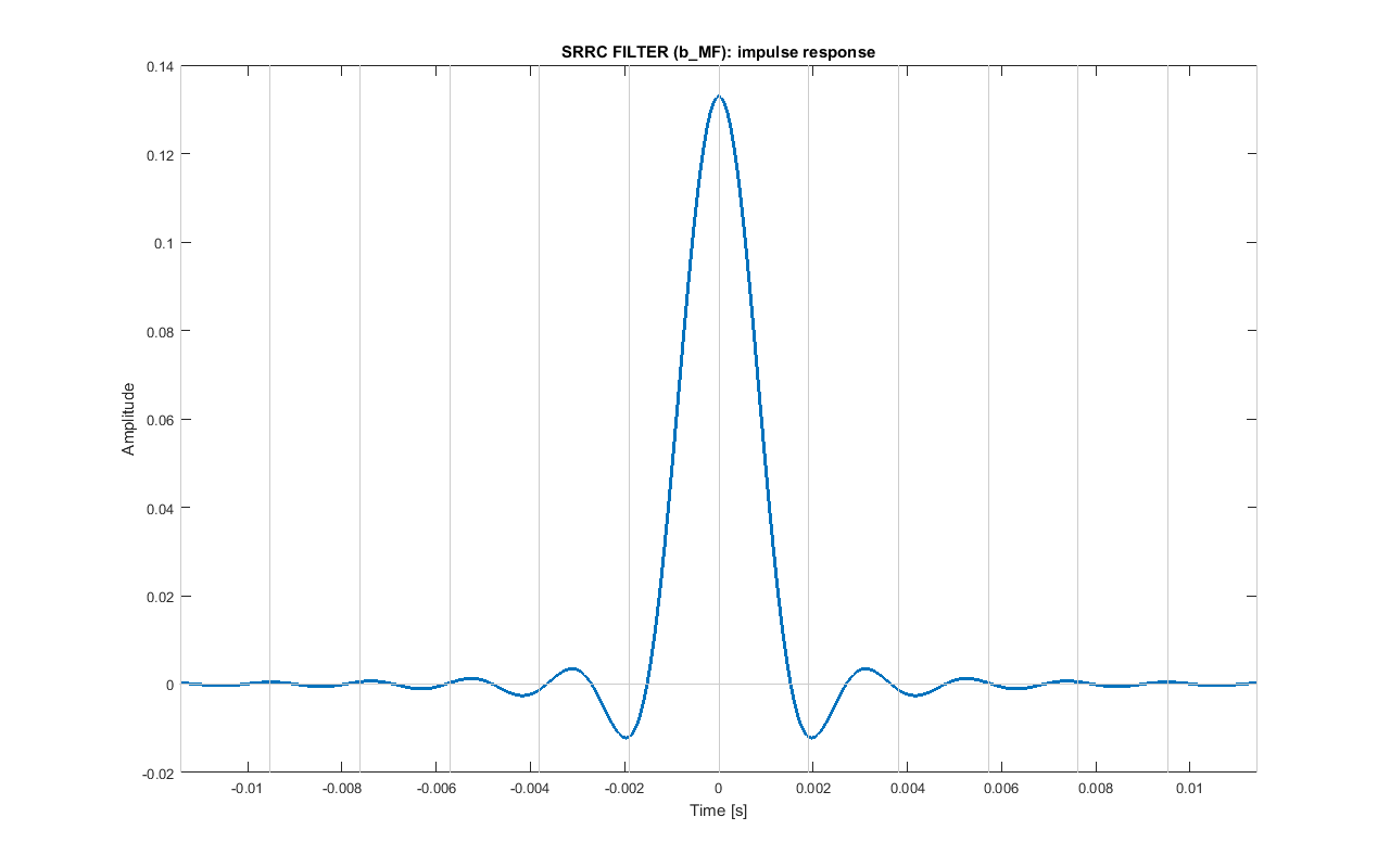 Impulse response of the pulse shaping SRRC filter.
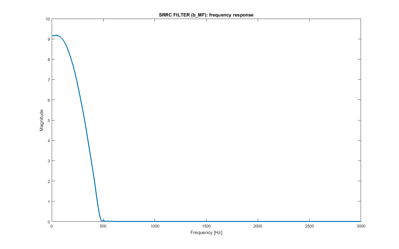 Frequency response of the pulse shaping SRRC filter b_MF. Only the frequency up to 3 kHz are shown.
The bandwidth of this baseband signal m_bb is:
BW_BB = BPS·(1+alpha_MF)/2 = 472.5 HzIf the filter is applied again to m_bb and the result is sampled every NS samples from a proper starting point, the original bipolar values of m_out are obtained. That's why at the receiver the filter will be matched with this one. The overall filter (pulse shaping SRRC filter followed by matched SRRC filter) is a raised cosine filter, that is a Nyquist filter, so it minimises intersymbol interference (ISI).
 Pulse shaping: example for the simplified bipolar signal m_out=[-1 -1 1 -1 -1 1 1 1 -1 1 -1 1 1 -1 1 -1 -1]. The interpolated signal m_bit is convolved with b_MF, obtaining signal m_bb (delays are not compensated here). If the result is convolved again with b_MF and sampled at NS (after compensating the delays of the two filters), the original values are obtained.
Signal Domain: Carrier Multiplication
The baseband signal m_bb is modulated using a carrier of frequency FC=18375 Hz, obtaining a BPSK signal m_psk.
m_psk = m_bb · sin(2π·FC·t)with t = [0 : TS : (length(m_bb)-1)·TS]
This has to be done for the entire of m_bb. However, for the samples that corresponds to the SYNC_preamble_bit bits, instead of FC, a different carrier frequency FC_SYN=18178 Hz is used. As explained later, this will help detecting the preamble.
The spectrum of m_psk signal is centered in FC and the occupied bandwidth is:
BW = BPS·(1+alpha_MF) = 945 HzFC was chosen so that BPS is a divisor of it: this way there is an integer number of carrier periods in a bit duration, that is FC/BPS=35.
 Carrier multiplication: example for the previous simplified bipolar signal m_out=[-1 -1 1 -1 -1 1 1 1 -1 1 -1 1 1 -1 1 -1 -1]. The baseband signal m_bb is multiplied by the carrier, obtaining signal m_psk.
Signal Domain: Bandpass filter
The modulated signal m_psk is then bandpass filtered with b_BP in the BW bandwidth to lower any unwanted frequencies, that are very small, though. The signal m_psk_out is obtained.
This same filter will be used at the receiver, in which, because of Doppler effect, the spectrum can be shifted of few Hz. That's why the passband of this filter is a bit wider than BW; instead of being in the range:
[FC - BW/2; FC + BW/2] = [17902; 18848] Hzit is in the range:
[FC - BW/2 - 25 Hz; FC + BW/2 + 25 Hz] = [17878; 18872] HzAlso, in the passband the maximum deviation from the desired value of 1 is set to 0.001.
Instead, the transition bands are set to BW/8, so the stopbands are:
[0; FC - BW/2 - 25 Hz - BW/8] = [0; 17759] Hz [FC + BW/2 + 25 + BW/8 Hz; FS/2] = [18991; 22050] HzIn the stopbands the maximum deviation from the desired value of 0 is set to 0.001.
The filter is designed as a Kaiser window FIR filter using Matlab functions kaiserord and fir1.
The length of this symmetric filter is 1355: this means that filtering produces a delay of delay_BP=677, not compensated here.
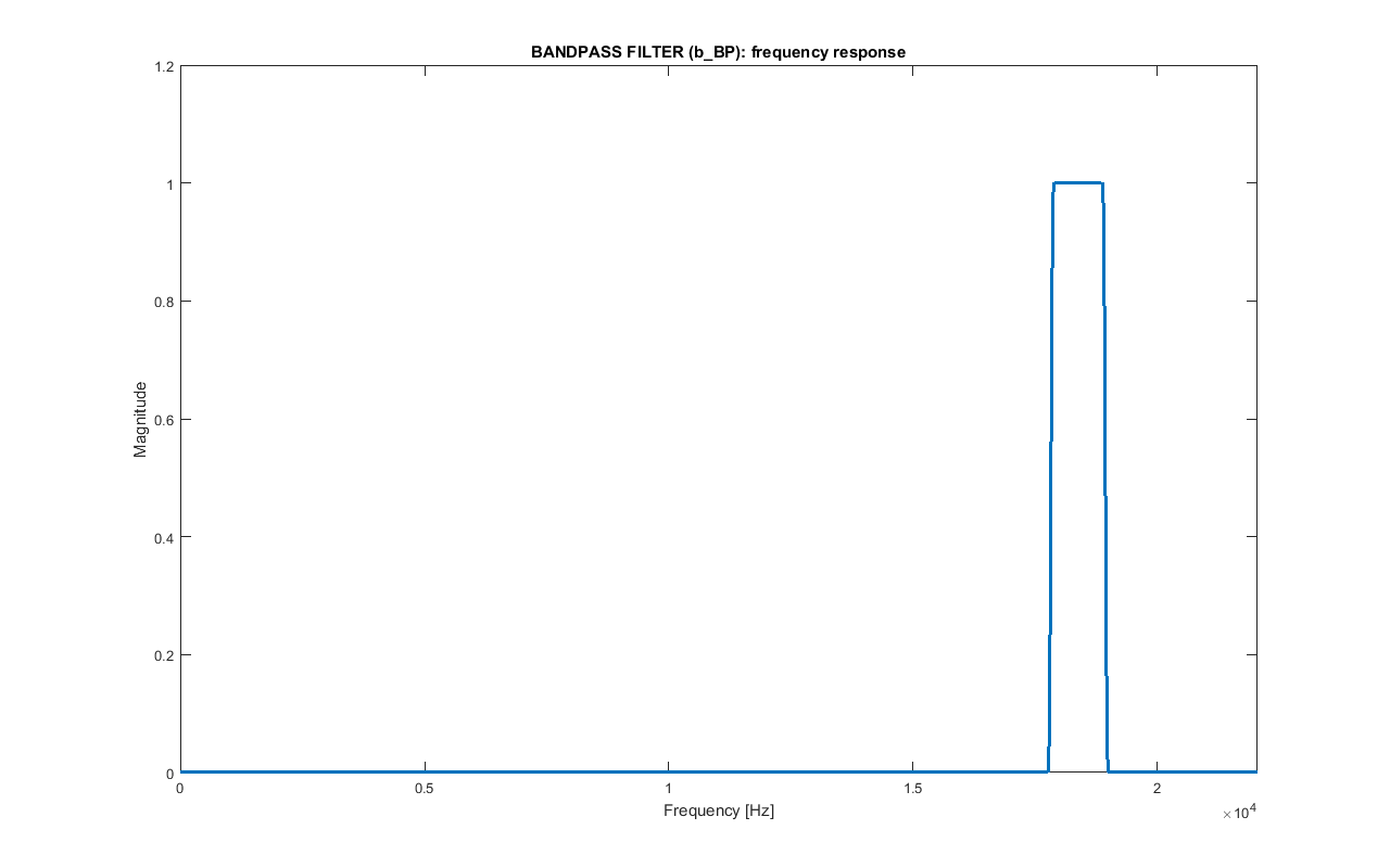 Frequency response of the bandpass filter b_BP.
Signal Domain: Normalization
The last thing to do to m_psk_bp is to normalize it: the audio signal with the embedded URL that will be produced must have a maximum amplitude of 1 (or, better, having some margin, of MAX_AUDIO=0.9) to avoid clipping that produces distortions and audible noise, so the amplitude of the PSK signal has to be chosen properly. The final signal m_psk_out is obtained.
This simply is done by normalizing the maximum of it to NORM_MAX_MSG=0.7:
m_psk_out = m_psk_bp/max(m_psk_bp) · NORM_MAX_MSGAt the receiver this normalization has to be undone. As the RMS of the BPSK signal is not influenced by bit values that much, when initializing the system, a random bit sequence has been generated and modulated using the same steps reported before. The RMS of the result (NORM_RMS_EST=0.077) is the expected value and is very similar to the one of m_psk_bp.
Synchronization Preamble Signal
As reported before, SYNC_preamble_bit is used as a synchronization bit sequence. First of all, at the receiver, after that the burst is detected, to facilitate the detection of the synchronization signal only the initial samples will be taken in account (more or less only the ones related to the two pad sequences and the synchronization code).
The pad sequence before SYNC_preamble_bit is needed to avoid losing important samples when detecting the edges of the signal. The pad sequence after SYNC_preamble_bit has been added so that what follows is known.
As the two pads are in fact non-modulated sinusoids, it is possible to modulate the synchronization code so that it is somehow orthogonal to them.
In general, for sampled sinusoidal segments of length N, orthogonality holds only for the harmonics of the sampling rate divided by N. In particular, only for those who have a whole number of periods in N samples and whose frequency can be written as:
f_k = k · FS / NIn this case, the carrier frequency FC is already of this kind by construction. Also, by having repeated each symbol of SYNC_preamble_seq0 K_SYN times, it is like the duration of each bit (and the relative sinusoidal signal) is NS_SYN = NS · K_SYN = 672 samples; as K_SYN is high, transition time interval between different value bits are negligible. Therefore, the carrier frequency to be used for SYNC_preamble_bit is defined as:
FC_SYN = (FC · NS_SYN / FS - 3) · FS / NS_SYN = 18178 HzAt the receiver the synchronization signal has to be known. So, when initializing the system this can be precomputed. In particular, as shown in the following figure, SYNC_preamble_seq (plus some more additional bits, that are like the pad values, used to avoid edge effect of convolution) are modulated (pulse shaping, carrier multiplication and bandpass filter). Then, the filters delays are compensated and the temporary bits' samples removed. The result is SYNC_preamble_psk_out.
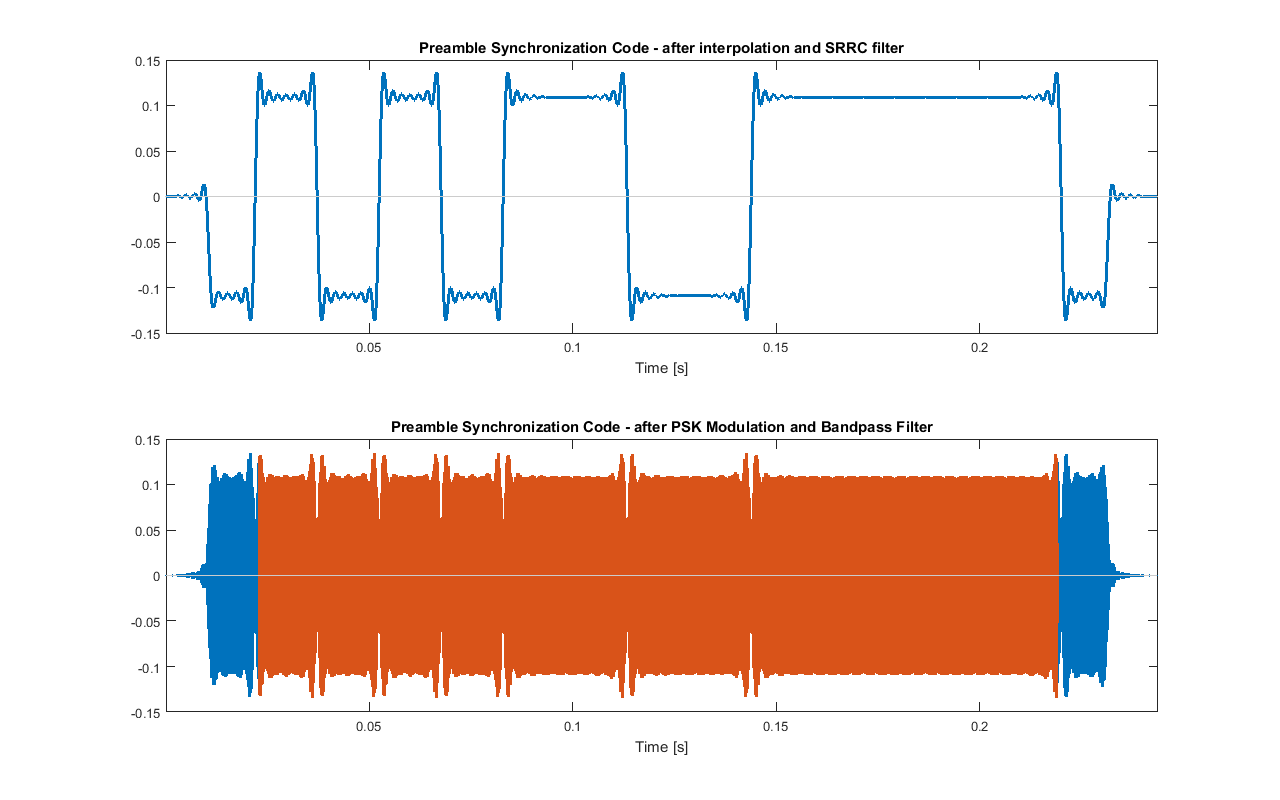 Modulation of SYNC_preamble_seq. The red signal is SYNC_preamble_psk_out.
To test the signal, beginning of m_psk_out (up to the end of the second pad) can be recreated. In the following figure it is shown the cross correlation between it and SYNC_preamble_psk_out
 Cross correlation between the beginning of m_psk_out and SYNC_preamble_psk_out. In green the position of the maximum of the cross correlation is shown (that is the detected position of the preamble)
In reality, the frequency would be shifted because of Doppler effect and there could be distortion, and the carrier are could not be orthogonal anymore. In any case, by doing some test, it turns out that this preamble works better than the one in which FC_SYN is equal to FC.
In the following figure it is shown that in fact the bits referred to the synchronization preamble have a slightly different frequency.
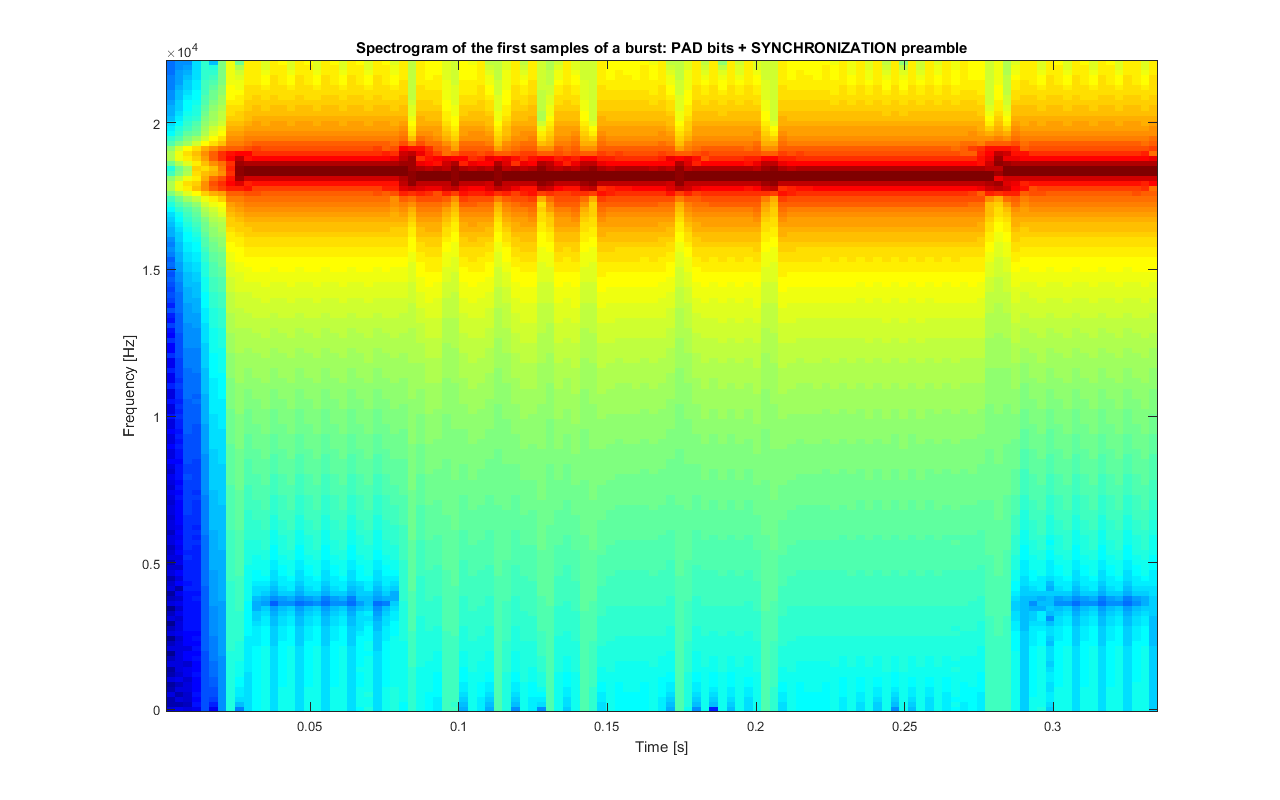 Spectrogram of the beginning of m_psk_out
Original Audio Preprocessing: Bandstop Filter
The last thing to do is to embed the modulated message m_psk_out in the stereo audio track audio_orig. Of course, this can be done only if the latter is long enough, and if the duration of the modulated message is shorter than the maximum allowed (MAX_T).
As mentioned earlier, a bandstop filter b_BS is applied to both channels of the original audio audio_orig to eliminate the frequencies used by the modulated message. As these are inaudible to most people, the resulting audio audio_bs shouldn't sound different.
Again, as at the receiver the frequencies of the recorded audio could be shifted of few Hertz because of Doppler effect and the filters will be fixed, the bandwidth of the filter used here is some Hertz wider than the one of the modulated message.
This filter is similar to b_BP: the same parameters and design methods have been used, the only difference is that its passband is the stopband and its stopbands are the passbands now.
The length of this symmetric filter is 1355: this means that filtering produces a delay of delay_BS=677 that is compensated by ignoring the first and the last delay_BS samples of the result of the convolution.
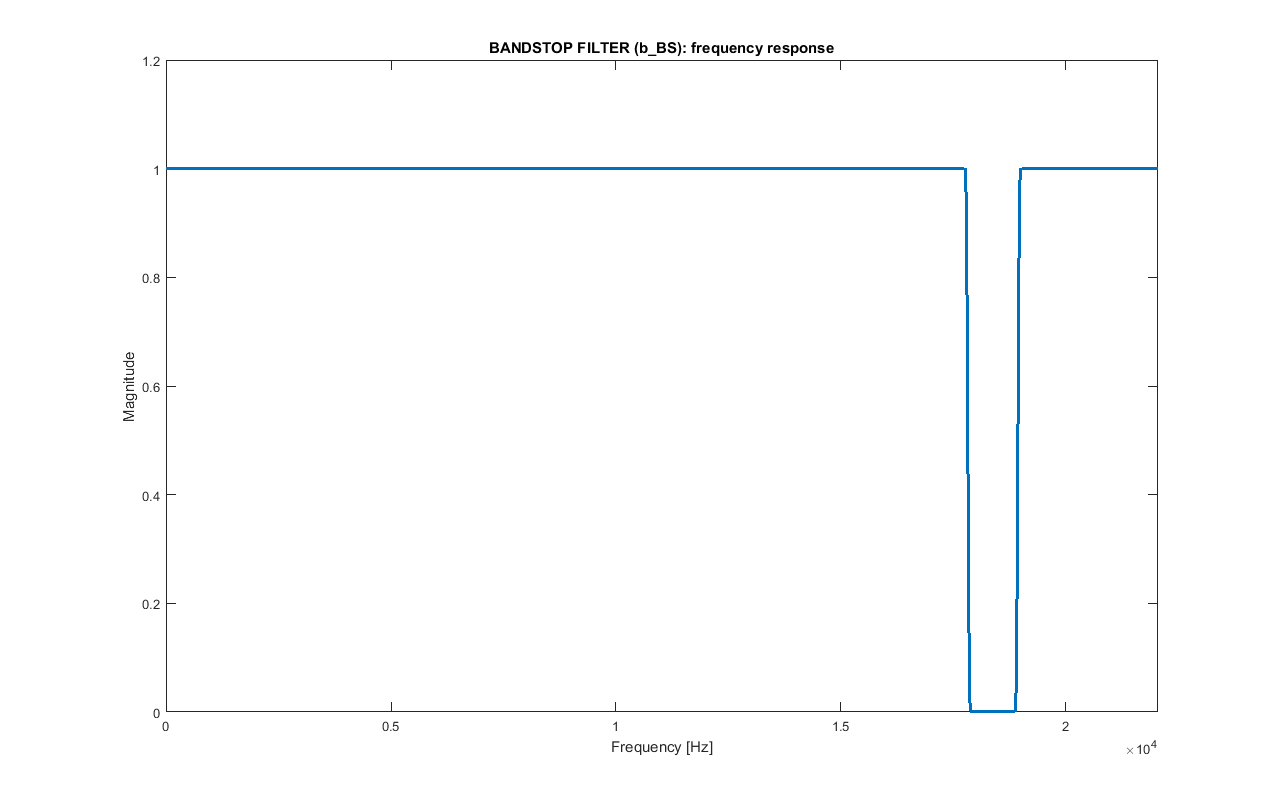 Frequency response of the bandstop filter b_BS.
Original audio preprocessing: normalization
Different audio tracks can have different volume. If the modulated signal is added to a high volume audio track, clipping is highly probable. So, an RMS normalization to NORM_RMS_AUDIO=0.05 is performed on both channels of audio_bs by doing the following:
audio_norm = audio_bs/rms_audio · NORM_RMS_AUDIOin which rms_audio is the mean of the RMS of the two channels of audio_bs. The signal audio_norm is obtained. Also, MAX_T is set to 4.75, that is a bit smaller than DELTA_T.
However, despite the low RMS, it may happen that the maximum of audio_norm is greater than a given value NORM_MAX_AUDIO=0.8 ≤ MAX_AUDIO. If this happens, an additional normalization to that maximum value is done.
audio_norm = audio_norm/max(audio_norm) · NORM_MAX_AUDIOAdding modulated message to the audio tracks
At this point, audio_norm and m_psk_out can be merged: the latter will be repeated more than once. In order to avoid interference by having the modulated message sound out of the two stereo speakers at the same time, the signal is added every DELTA_T = 5 sec seconds once in the left channel, then in the right one, then in the left one again and so on, as shown in the image below.
As at every message insertion the resulting sound can be above the maximum level allowed MAX_AUDIO, if this occurs amplitude of m_psk_out is reduced in that particular point by a factor smaller than 1: this happens only when needed, for example, when there is a portion of audio_norm with high volume. If for some reasons in a certain time interval the m_psk_out still cannot be inserted because of amplitude constraints violation, that it is skipped (this should not happen, though).
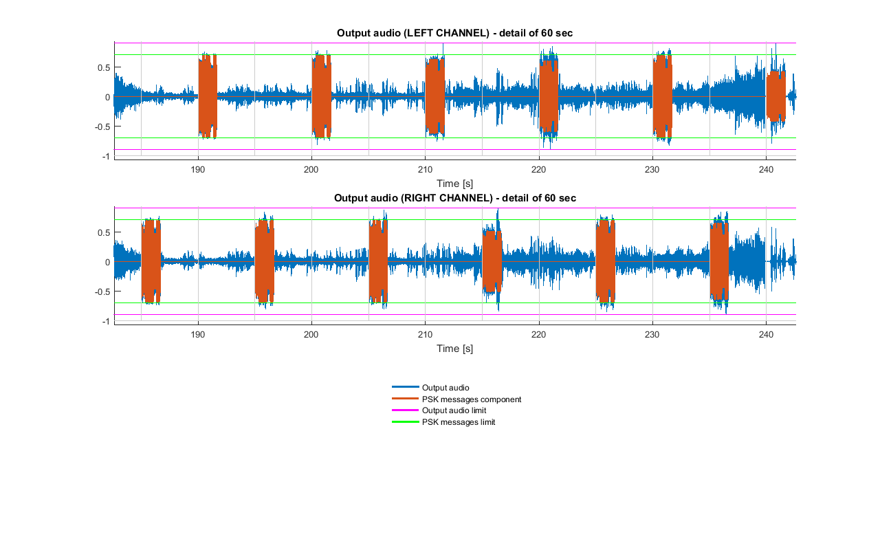 Example of PSK messages insertion. Vertical gray line are spaced DELTA_T seconds. Also, here it can be seen that some bursts were reduced in amplitude to fulfil the constraint on the output audio.
The audio track with the URL embedded is now ready to be used: the high frequency modulation signal should not be audible to most people.
Note that if the speaker used to reproduce the track are not of high quality, when listening to the audio at high volume there can be distortions and audible noise: these are caused by clipping due to waveform that are driven to the speakers at levels beyond maximum amplifier levels.
From AUDIO back to URL
Signal Domain: Bandpass Filter
While the audio with the embedded URL is being played, a device with a proper mic records in mono REC_T=2·DELTA_T = 10 sec seconds of it into the array r_rec: as a PSK signal is inserted every DELTA_T seconds, both the left and right messages will be captured in the same audio track and it is ensured that there is a complete message, provided that the audio track that is being recorded isn't stopped or is changed. In particular, there can be two complete bursts or one complete and two partial ones.
 When recording REC_T seconds (red rectangles in the figure) of the audio with the embedded message signals in mono (blue rectangles in the figure), there can be two possible situations: (A) two full message signal are present, (B) one full message signal and two partial ones are present
To remove any unwanted frequency that acts as noise, the result is filtered with the same bandpass filter used before, that is b_BP, and the delay is compensated: the signal r_rec_bp is obtained. As the bandwidth of this filter is few Hertz larger than the theoretical one, if the spectrum is shifted because of Doppler effect, no valid signal is filtered out.
Signal Domain: PSK signal Detection
The next step is to detect a complete PSK message in r_rec_bp. Given that there can be only two cases (two complete bursts or one complete and two partial ones) the following algorithm is used. The parameters have been chosen by trying different values and choosing the ones with better results.
Firstly, the envelope env of the logarithm of squared r_rec_bp (obtained by squaring each sample) is estimated by dividing it into blocks of 10·NS samples and taking for each of these the maximum in the respective block. Then, the result is smoothed by using a median filter of order about 200·NS, obtaining signal med.
After that, the resulting signal is saturated into signal sat0 by using a threshold th: values above it are set to abs(th) and the others to 0. This threshold is defined from the range of med:
th=(max(med)-min(med))/3+min(med)Now, each sequence of non-zero samples of sat0 should indicate the presence of a potential burst. The ones whose length is less than the minimum expected (((RS_N*RS_S)+(CV_K-1))*CV_N + (LEN_N+LEN_CRC)*LEN_REP + length(PAD) + length(SYNC_preamble_bit), ignoring pad bits at the edges), caused by noise in the used bandwidth, are set to 0. The signal sat is obtained.
The PSK signal burst r_det is detected by using sat: boundaries are found by finding the complete burst with the greater total mean envelope.
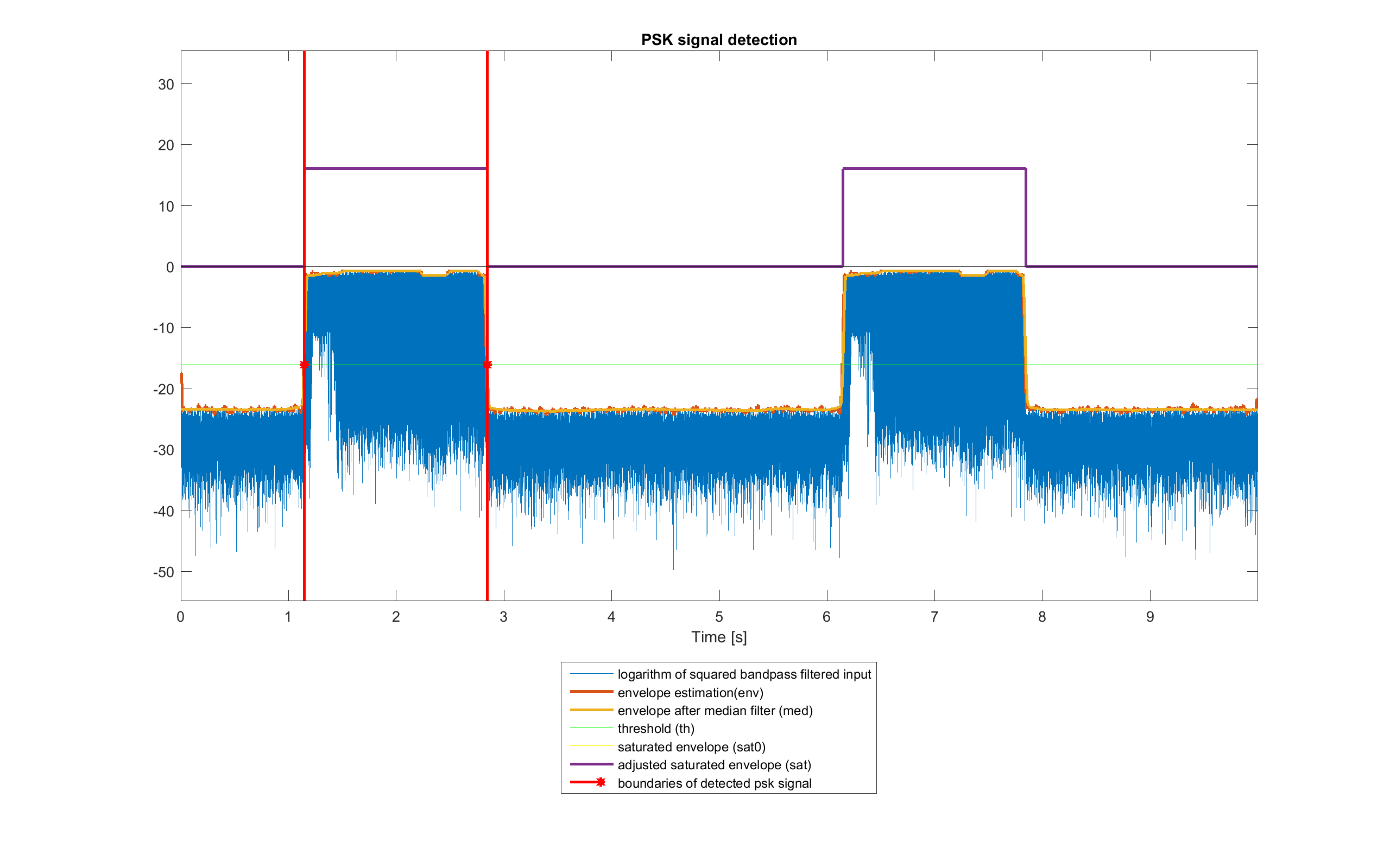 Example of PSK message burst detection in ideal conditions
Signal Domain: Normalization
Due to transmission, the signal r_det has a lower amplitude than the expected one. The RMS of the signal should be around NORM_RMS_EST. So, the RMS normalized signal r_norm is obtained by:
r_norm=r_det/rms(r_det)·NORM_RMS_EST;Signal Domain: Preamble Synchronization
Now, to know the exact starting point of sampling, the position of the preamble, that should be similar to SYNC_preamble_psk_out in r_norm has to be determined.
First of all, only the first length(SYNC_preamble_psk_out)+2*length(PAD) bits of the signal are considered, so the following are defined:
XC_N = NS · (length(SYNC_preamble_psk_out) + 2·length(PAD) + 1) xc_r_norm0 = r_norm(1:XC_N)Despite the preamble should be orthogonal to the part of the signal of the two pads, because of distortion due to the channel, the cross correlation between xc_r_norm0 and the expected preamble SYNC_preamble_psk_out may not be the one that is expected. So, as the part of the signal at the edge of xc_r_norm0 should be sinusoidal with frequency FC and the preamble doesn't have significant component in there, this can be removed by using a notch filter in that frequency. In general this filter has a zero-phase delay only in FC: to have an overall zero-phase delay, Matlab function filtfilt can be used; as this produces ringing at the edge of the signal, the amplitude of xc_r_norm0 is reduced at the edges before filtering. The result is xc_r_norm.
 Zero-phase notch filtering of xc_r_norm0 in ideal conditions
As the signals are sampled and carrier frequency is high, there are only few samples for each period of it. So, xc_r_norm is interpolated by XC_INTN = 10: this helps detecting the preamble. The expected one (SYNC_preamble_psk_out) is interpolated too. The signals xc_r_norm_int and SYNC_preamble_psk_out_int are obtained.
After that, the cross correlation between xc_r_norm_int and SYNC_preamble_psk_out_int is computed, and only the non-negative lags xc_lags and the relative values xc_c are kept.
Now the maximum of xc_c (xc_max) and the relative lag (xc_max_lag) is found. From this last value, if indexes start from 1, the shift (in the new sampling rate) can be computed as:
xc_shift_int = xc_max_lag - 1This value determines the position of the preamble. However, because of distortion of the signal and reflections, it can happen that there are more than one significant peak in the cross correlation (spaced of about NS·K_SYN·XC_INTN)· samples), and the detected one is not the real starting point. To mitigate this, another maximum of the envelope of xc_c is found, considering points close to it. If that new peak is great enough in value in respect to xc_max, the samples of xc_r_norm_int close to that point are analysed to see if this should be taken as the new xc_max_lag; in that case, the new xc_shift_int is computed.
 Synchronization of the preamble
If xc_shift_int/XC_INTN is integer, the synchronized signal is:
r_syn = r_norm(xc_shift_int/XC_INTN+1:end)Otherwise, r_norm is interpolated by XC_INTN into r_norm_int. The interpolated synchronized signal is:
r_syn_int = r_norm_int(xc_shift_int+1:end)and then is sampled again by XC_INTN to obtain r_syn.
Lastly, the preamble is removed from the signal, obtaining r_psk (the part that is related to the pad after the preamble is kept and will be removed later).
Signal Domain: Carrier Recovery
At this point, demodulation has to be performed. Because of differential encoding, a non-coherent demodulator can be used: this is needed to compensate Doppler effect and make phase offset negligible. The first things to do are to recover the carrier, to multiply it to the PSK signal and to apply the matched filter: a quadrature scheme has been used.
 Demodulation scheme
Three variation have been considered, each with some advantages and disadvantages:
- The first one uses as carriers the ideal expected ones, so it is simple and fast to implement. However, if there are some phase or frequency offsets, the constellation of the sampled symbols rotates: differential decoding is used to compensate this. This will be denoted by IC.
- The second one recovers the carriers from the received PSK signal, so some more computation needs to be done. If there are some phase or frequency offsets, these are compensated, within some limits. After that, differential decoding is performed too. This will be denoted by RC.
- The third one doesn't use real carriers, instead these are obtained from a delayed version of the PSK signal (so, they are PSK signals, too). This method is more affected by noise (because the "carriers" are as noisy as the signal). The sampled symbols are already differential decoded, so a later differential decoding isn't needed. This will be denoted by NC.
From now on, to indicate the same signals for the three version, _k will be appended to their names; k is ID, RC or NC depending of which of the three it is referred to.
Method IC
In the first method (IC), the carriers have the same fixed frequency used in the modulator:
carrier_IC = cos(2π·FC·t) carrier__90_IC = sin(2π·FC·t)with t = [0 : TS : (length(r_psk)-1)·TS]
Method RC
In the second method (RC), the squaring loop carrier recovery has been used:
 Carrier recovery scheme for the RC method.
This is based on the fact that a BPSK signal can be represented as:
m_psk(t)=A(t)·sin(2π·FC·t + h·π) with h=0 or 1When this signal is squared, the following is obtained:
m_psk^2(t)=A^2(t)·(1 - cos(2π·2·FC·t + 2·h·π)) = = A^2(t)·(1 - cos(2π·2·FC·t))So, the modulation can be removed. The component at double frequency can be extracted by using a bandpass filter. After that, a frequency division has to be applied to it, to get the recovered carrier: here, this is simply done by obtaining a square signal from double frequency carrier, performing frequency division (so another square wave is obtained) and keeping only the first harmonic of the result, to get back a sinusoidal one.
In order to get complex symbols comparable to the other methods, it is normalized to the RMS of carrier_IC and quadrature one is obtained by delaying the phase by -π/2:
carrier_RC = carrier_RC · rms(carrier_IC) / rms(carrier_RC) carrier_90_RC = phase_delay(carrier_RC, -π/2)Method NC
In the third method (NC), the in-phase carrier is simply the PSK signal delayed by NS:
carrier_NC0 = r_psk(NS+1:end)This carrier is sufficient for this BPSK demodulator. However, in order to get complex symbols comparable to the other methods, it is normalized to the RMS of carrier_IC and the quadrature one is obtained by delaying the phase by -π/2:
carrier_NC = carrier_NC0 · rms(carrier_IC) / rms(carrier_NC0) carrier_90_NC = phase_delay(carrier_NC, -π/2)Signal Domain: Carrier Multiplication and SRRC Matched Filter
Now, for each of the three version, the signal r_psk has to be multiplied by both the recovered carrier and quadrature one, producing the two signals r_psk_cos_k and r_psk_sin_k. Note that for the NC variant, r_psk(1:end-NS) has to be used, instead of the full signal.
r_psk_cos_k = 2 · r_psk · carrier_k r_psk_sin_k = 2 · r_psk · carrier_90_kAfter that, a lowpass filter is applied to both. This filter is matched to the pulse shaping filter used at the modulator, and is the same filter b_MF, so that the result of the two filters is a Nyquist raised cosine filter that minimize ISI. The two results are the signals r_psk_i_k and r_psk_q_k respectively.
The reason of this follows from Werner formulas. A BPSK signal can be represented as m_bb(t)·sin(2π·FC·t + ɸ) and the expected carrier as sin(2π·FC·t + ɸ); in ideal conditions (no noise nor Doppler distortion), the same calculation produces:
2 · m_bb(t)·sin(2π·FC·t + ɸ) · sin(2π·FC·t + ɸ') = m_bb(t) · [cos((2π·FC ·t + ɸ) - (2π·FC ·t + ɸ')) - cos((2π·FC ·t + ɸ) + (2π·FC·t + ɸ'))] = m_bb(t) · [cos(ɸ - ɸ')) - cos(2π·2·FC ·t + ɸ + ɸ')]A baseband signal proportional to the original baseband signal and one at double the carrier frequency are obtained. Note that actually the component at 2·FC=36750 Hz is aliased to FS-2·FC=7350 Hz, but this is not a problem since the two do not interfere and only the lowpass component will be filtered and used:
m_bb(t) · cos(ɸ - ɸ')However, in reality there are also noise, time-variant phase shifts and time-variant frequency offset due to Doppler, so the result is a distorted version of m_bb:
m_bb(t) · cos(2π·ΔFC(t) ·t + Δɸ(t)) + noiseMessage Domain: Sampling
The signals r_psk_i_k and r_psk_q_k are downsampled by taking a sample every NS producing the sample arrays r_samp_all_i_k and r_samp_all_q_k. No timing recovery is made, as the first sample is synchronized and the Doppler effect doesn't affect bitrate too much.
At this point the extra pad samples are removed from the sequence, and r_samp_i_k and r_samp_q_k are obtained: these are the in phase and quadrature component of the complex symbols related to the bit to recover.
All of this is done for each of the three demodulation schemes.
 Demodulation results in ideal conditions over a limited time interval for each of the three method IC, RC and NC. Both in-phase and quadrature components are shown. Blue lines are the results of carrier multiplications, red line are the matched filtered signals and yellow dots are the sampled data
Message Domain: Differential Decoding and Hard Decision
The samples of r_samp_i_k and r_samp_q_k of the versions IC and RC are differentially encoded, so the decoding is done now. The effect is to mitigate, when possible, the distortion due to the carriers' time-variant phase shifts and time-variant frequency offset due to Doppler. Instead, this is not needed for the NC signals, since they are already differentially decoded.
This can be done by computing the phase difference between two consecutive complex symbols and taking the associated bit value:
ΔΦ = 0° ± 90° ↔ 0 bit ΔΦ = 180° ± 90° ↔ 1 bitInstead of calculating the phase of the complex symbols, the following approach can be used. The results are the sample sequences r_diff_i_{IC,RC} and r_diff_q_{IC,RC}. The latter is not needed for the next stages when using DBPSK, although it can be useful to show constellation plots, etc.
for n=1, 2, ..., length(r_samp_i(): r_diff_i(n) = r_samp_i(n) · r_samp_i(n+1) + r_samp_q(n) · r_samp_q(n+1) r_diff_q(n) = r_samp_q(n) · r_samp_i(n+1) - r_samp_i(n) · r_samp_q(n+1)Instead, as anticipated before, for the NC version:
r_diff_i_NC(n) = r_samp_i_NC(n) r_diff_q_NC(n) = r_samp_q_NC(n)At this point the samples, now even for the NC signals, have to be hard decoded and the bit sequences r_bit_k are obtained for each of the three version:
r_diff_i(n) ⋝ 0 ↔ r_bit(n) = 0 r_diff_i(n) < 0 ↔ r_bit(n) = 1The constellation of the differentially decoded samples is shown below.
 Constellation region of the differentially decoded samples. Red dot are the expected symbols.
The bit sequences r_bit_k, if no errors are present, should be equal to the array m_bit, defined previously (although some extra bits can be present and will be removed in the following steps). Their first (LEN_ENC+LEN_CRC)·LEN_REP bits represent the header, the others the payload. From now on, the same operations are performed in the arrays obtained from the three methods.
Message Domain: Header Repetition Decoding
Firstly, there is to do the repetition decoding of the header. If each bit was repeated LEN_REP times, now the header has to be divided into blocks of the same size, and for each of them, the sum of the values has to be computed (bits are considered as decimal numbers). If this result is greater than LEN_REP/2, the block is decoded as bit 1, otherwise as bit 0.
Message Domain: Header CRC Check
The last LEN_CRC bits of the repetition decoded headers are their CRC, so their validity can be checked.
This is simply done by taking the non-CRC bits of each decoded header and recomputing the CRC: if the result is equal to the CRC bits of the array, it can be assumed that it is correct (there are some non-detectable errors, that may be very rare or not depending on the size of the CRC and of data). Again, more details can be found here.
Message Domain: Decode the number of RS blocks and get the real length of the payload
If the test done in the previous step is passed, the CRC bits are removed and the others are converted to their decimal representation that is the number of Reed-Solomon blocks that are encoded in the payload (n_rs_k). From this, the number of bits of the real payload (len_k) can be computed as:
len_k = (n_rs_k · (RS_N · RS_S) + (CV_K-1)) · CV_NThis number should be correct. However, as the header CRC has few bits, the probability of false positive is a bit higher (but not too much, since there are only few non-CRC bits). If len_k is greater than the actual length of the payload of r_bit_k, an error has occurred in the detection of the burst edges in the previous stages or in the decoding of n_rs_k.
In the latter case the payload might still lead to a correct result. So, instead of throwing away it, an attempt is made by taking n_rs_k as the one that matches the best, that is the one associated to the greatest message that fits. The probability of this number to be correct increases if Reed-Solomon codewords have bigger size, as errors in the detection of the boundaries of the burst from the recorded audio have less impact. For the same reasons, this is done even if the CRC test is not passed.
After this the header bits are removed from r_bit_k and the first len_k ones are taken from the payloads of the three, obtaining the arrays r_conv_k, that, if no errors are present, should be equal to the array m_conv, defined previously.
Message Domain: Payload Viterbi decoding
At this point, the payloads of the three r_conv_k, that are protected by convolutional codes, are decoded by using the Viterbi algorithm, that estimates the more likely original sequence, producing the arrays r_rs_k, that, if no errors are present, should be equal to the array m_rs, defined previously.
More details can be found here and here.
Message Domain: Payload Reed-Solomon decoding
Now, the three r_rs_k, that are protected by Reed-Solomon codes, are decoded producing the arrays r_crc_k, that, if no errors are present, should be equal to the array m_crc, defined previously.
The arrays r_rs_k are divided into blocks of RS_N · RS_S bits. For each block, that has RS_N symbols of RS_S bits, when possible, the errors in it are detected and sometimes also corrected. Then, as this is a systematic code, only the first RS_K · RS_S bits of the result are kept.
Again, more information about how the decoding works and its implementation can be found here and here.
Message Domain: Payload CRC check
The last two stages of the system assume that there are no errors, so the three r_crc_k have to be checked to see if some of them are still present. So, just like the ones in the headers, their CRCs, that are their last CRC_N bits, are verified.
If the test is passed, the CRC bits are removed (obtaining r_rle_zp_k, that, if no errors are present, should be equal to the array m_rle_zp, defined previously) and the following step can be performed.
Message Domain: Payload RLE decoding
Now it is time to do the custom RLE decoding, in which it has to be undone what was done in the same stage in URL TO AUDIO. The first PRE_LEN elements of r_rle_zp_k are kept as the first bits of the result, as the same was done in the encoding.
After that, there is always the encoding of a runlength of 1. Its length is found by counting the number of zeros until the first 1, that has to be included in the calculation, is found. When this happens, a runlength of this size is appended to the previous result.
After this, there is the encoding of the runlength of 0: if there is a 1, a 00 is appended to the previous result, otherwise a single 0 is appended.
Then, there is again the decoding of a runlength of 1 and all repeats.
Note that in the end two consecutive spaces of 00 should be obtained. However, the second one is treated as an encoding of a runlength 1, even if it is not. As by construction there is no ending 1 bit, the algorithm provides that if this happens an ending space of 00 has to be appended, instead.
The arrays r_var_zp_k are obtained, that, if no errors are present, should be equal to the array m_var, defined previously.
Message Domain: Payload Varicode decoding
It is now possible to get the text by doing the Varicode decoding of the three r_var_zp_k to get the recovered text text_rec_k.
This is done by getting the relative starting string that is associated to the first PRE_LEN bits. Then, scanning the bit array, when two zeros (the Varicode space code) are found, the string pattern associated to the found Varicode code is appended. This ends when more than two consecutive zeros are found.
If no error has occurred in the process, the URL is retrieved correctly and is equal to text_orig, defined previously.