When analysing sleep quality, it is important to consider the homeostasis of the sleep phases, especially the REM phase. The latter, which takes about 20-25% of the nocturnal cycle, should in fact neither be reduced by intermediate nocturnal awakenings, since it could cause states of disorientation and reduce memory and the ability to concentrate, nor prolonged as it would produce an excessive brain activity with significant repercussions on the affective-behavioral side (greater irritability, depressive and anxious symptoms).
Due to these reasons, it is considered useful to develop a specific device that can support the sleep quality avoiding the possibility of being awakened during a phase which is not strictly suitable.
Sleep is characterized by a cyclical alternation of 5 phases divided into two macro-moments:
NRem phase. It is the first macro-phase of sleep, it lasts about 75% of total sleep, in which there are no rapid eye movements. In turn, it consists of 4 stages lasting from a minimum of 5 minutes to a maximum of 15 minutes. In the transition from one of these periods to another, sleep gradually deepens:
Rem phase. In this phase, brain activity awakens with an alternation of waves (Theta, Alpha and Beta), while the eyes begin to move rapidly. Dreams occur in this stage of active sleep, accompanied by a gradual but sensitive increase in blood flow, breathing and brain activity. In fact, from the monitoring of subjects in the rem phase, the electroencephalogram shows how the brain is as active as in a waking state, so much so that oxygen and glucose are consumed as if one were awake. Furthermore, one of the characteristics of this phase is that the muscles of the legs and arms are paralyzed. This phenomenon of muscular “atony” has the function of preventing rash and unpredictable movements, possibly generated by the dream.
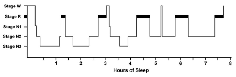
Rem and NRem phases alternate about 4-6 times during the night for a total duration of an hour and a half, resulting in the so-called sleep cycles. In addition to an adequate duration, in order for sleep to be regenerating and restful, this cyclical structure characterized by the alternation of phases must be respected.
Compared to what has been said, however, the limits of this tool must be considered. In fact, sleep is a complex phenomenon that requires the skills of specialized figures (specialists in Sleep Medicine) and the carrying out of Polysomnography. The latter, specifically, is the only exam capable of recognizing the macro-structure of sleep through:
The smart alarm device (also called Central Device or Alarm Clock) is powered by an Arduino Nano BLE which includes a BLE (Bluetooth Low Energy) 5.0 module. Its task is to receive information on the user's sleep status and to sound the alarm at the correct time. If the alarm clock fails to connect to the peripheral device, it will implement the basic functionality of a standard alarm clock.
Users can set the alarm time through the user interface, consisting of the 4x4 keypad. In addition, some ceramic capacitors were added on the row pins to delete external interferences, which had brought unpredicted behaviors to the keys during the testing phase. As shown in the figure below, by pressing the C key, the user can set the deadline (aka target time) for the alarm to be played: if this time is reached, the user will be woken up, no matter the sleep stage he’s in. When the alarm is ringing, the user can turn it off using the D button. Furthermore, the user can turn ON or OFF the alarm functionality with an A button press and change the current time by clicking the B button; this option can be very useful when the time shifts from legal to solar and vice versa.
The 20x4 LCD display normally shows current date, time and notifies if the alarm time is set (when it is, a bell symbol is shown). As the user navigates in the menus, the LCD also displays the status information related to the specific operation. There’s also a Real Time Clock (RTC), which gives the time data using an internal oscillator and a 3V battery to keep the RTC running when the general system is turned off.
The speaker plays a custom alarm using an offline made note-to-frequency conversion via software; moreover, an amplifier is needed in this operation, because the output current from the Arduino nano pins is not high enough. For this reason, we introduced an amplification stage composed of one NPN bipolar transistor in common emitter configuration and the bias resistors.
The external case is made with recycled wood panels and the internal layout is optimized and kept tidy using custom-length wires (e.g., the ethernet cable used for the keypad connections). To obtain the night sleep trend and to plot the measurements, an additional feature was added: the data can be conveyed to the serial output and processed by the external Matlab script.
The wearable device is powered by an Arduino Nano 33 IoT board and a 9V rechargeable battery, both housed in a 3D-printed plastic case. The Nano 33 IoT board includes the Inertial Measurement Unit (IMU) and the BLE module, which enables wireless data transmission from the wearable to the Alarm Clock.
The IMU module provides instant acceleration values in 3-axis dimension (x,y,z), composing a 3D vector. As explained in the following sections, these acceleration values are locally processed through arithmetical operations (here, one of the main targets is measurement noise reduction [1]), then they are transmitted to the Central Device. To notify the user's sleep state, a flag called "SNREM" is also sent to the alarm clock.
An HR sensor (MAX30102) is present in the schematics below, as it was involved in early test phases; check section Future works for more details on the matter.
The light sleep recognition algorithm adopted and presented in [1] detects non-REM stages via a mechanism of thresholds. The entire sleep time is divided into time windows of a fixed duration: in the tests we conducted, we used 30 min windows. Inside a time window, every read and computed value is kept in order through the \(k\) index, which is set to 0 at the end of the window.
First, raw acceleration values, which are 3 dimensional arrays \((x,\,y,\,z)\) need to be processed in order to remove measurement noise and to obtain scalar data. To achieve this, we slightly modified the method adopted in [1], as we normalize the acceleration values in the three axis, dividing them by the module of the 3D vector.
$$ \text{distance} = \sqrt{x^2(k)+y^2(k)+z^2(k)} \tag{1} $$
$$ n_i(k) = i/\text{distance} \, \quad i = x(k),\, y(k),\, z(k) \tag{2} $$
The md (Manhattan Distance) value is then computed as done in [1], considering previously and currently detected acceleration values, by the following:
$$ \text{md(k)} = \sum_{i=x,y,z} \mid n_i(k)-n_i(k-1)\mid \tag{3} $$
Sleep stage recognition is possible through a simple evaluation of the md value:
$$ \text{stage}(k) = \begin{cases} S_{NREM} & \text{if} \; T_{min} \leq \text{md}(k) \leq T_{max}\\ S_{REM} & \text{otherwise}\\ \end{cases} \tag{4} $$
\(T_{max}\) and \(T_{min}\) being the maximum and the minimum threshold. If the md value is between these two, then a non-REM stage is detected.
Threshold computation. The two thresholds are determined as follows:
The complete algorithm is shown in the Figure: the Tmax_history array is used to store all \(T_{max}\) values, to find the minimum between them and assign it to \(T_{min}\).
The central device constantly compares the current time to the alarm time set by the user (aka set time), in order to enter into the “alarm window” when necessary. In this window, the alarm is played as the first SNREM value is received by the central device. If no SNREM value is collected, the window ends with the alarm time set by the user: at that moment, the user must be awakened even if he is in a REM sleep state. The tests were conducted activating the alarm window 15 mins or 30 mins before the set time.
Light sleep detection. Since the acceleration-based algorithm can only detect light-sleep phases (SNREM), only those are considered when evaluating the experimental results of the Smart Alarm device. The outcomes are in line with those of popular sleep-stage detecting apps available on mobile stores, the majority of which perform a microphone-based analysis. These comparisons are shown in the following pictures: the continous line depicts the sleep trend according to a popular mobile app, while the diamonds point out the time instants in which Non-Rem statuses (SNREM, i.e. light sleep stages) where detected by the Smart Alarm.
Alarm function. As a consequence of the reliable light sleep detection results, it can be noticed that the patient is awakened as a non-Rem status is observed in the last 30 minutes before the set time.
To further improve the light sleep phase recognition capabilities and extend it to full sleep stage detection, heart rate (HR) data can be added to the algorithm. During the early phases of development, the implementation of an HR sensor was experimented, but it was ultimately left out due to poor measure reliability. Indeed, sudden drops in accuracy were exposed when the HR sensor was subjected to long test cycles and motion. Since sleep periods usually last more than a few hours, the feature was dropped as final decision.
As shown in the picture below, the HR results in short time periods are acceptable. When one HR sample is acquired by the sensor, it is stored in the appropriate array. As said array is filled up, an ascending order sorting algorithm is performed, then the median is computed. In earlier tests the mean value was determined, though this solution didn’t provide enough protection from outliers and measure inconstancy.