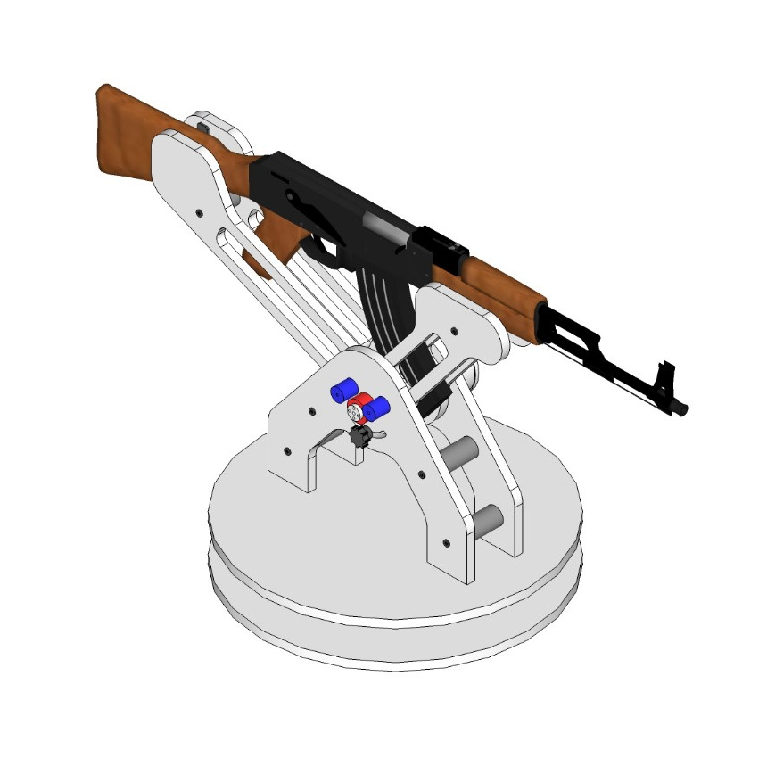
Designing the structure housing the rifle in SketchUp
Designing the structure housing the rifle in SketchUp
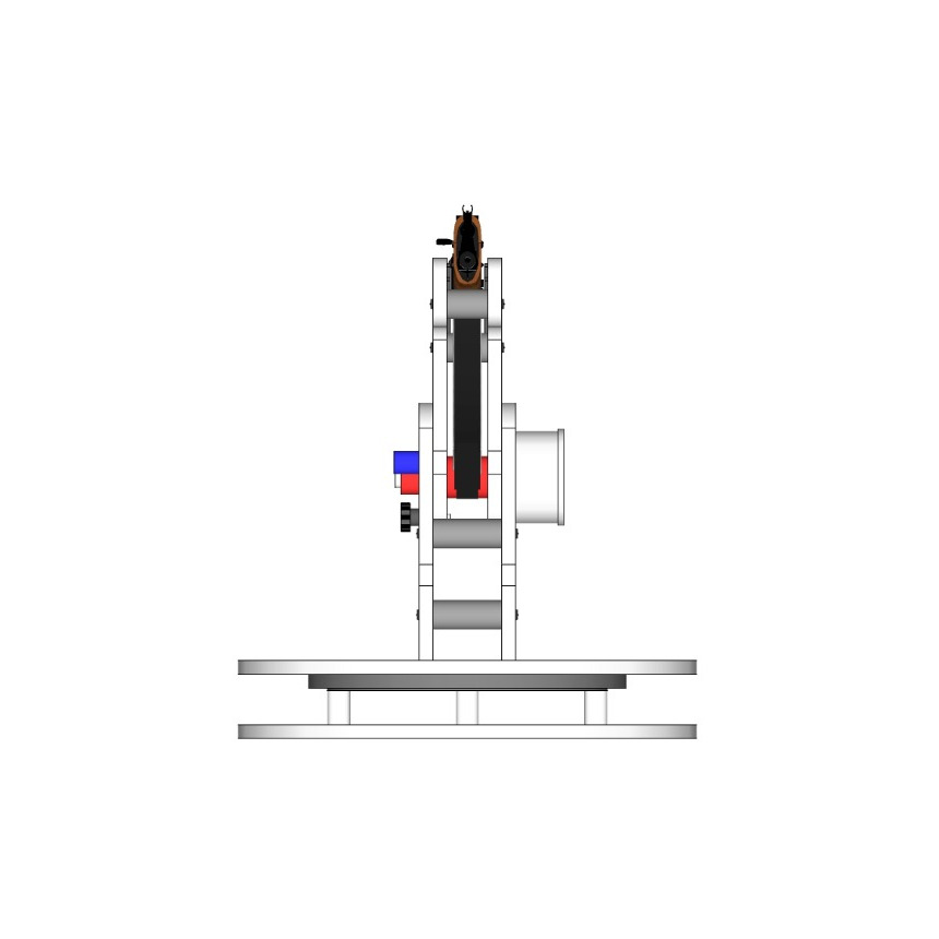
Designing the structure housing the rifle in SketchUp
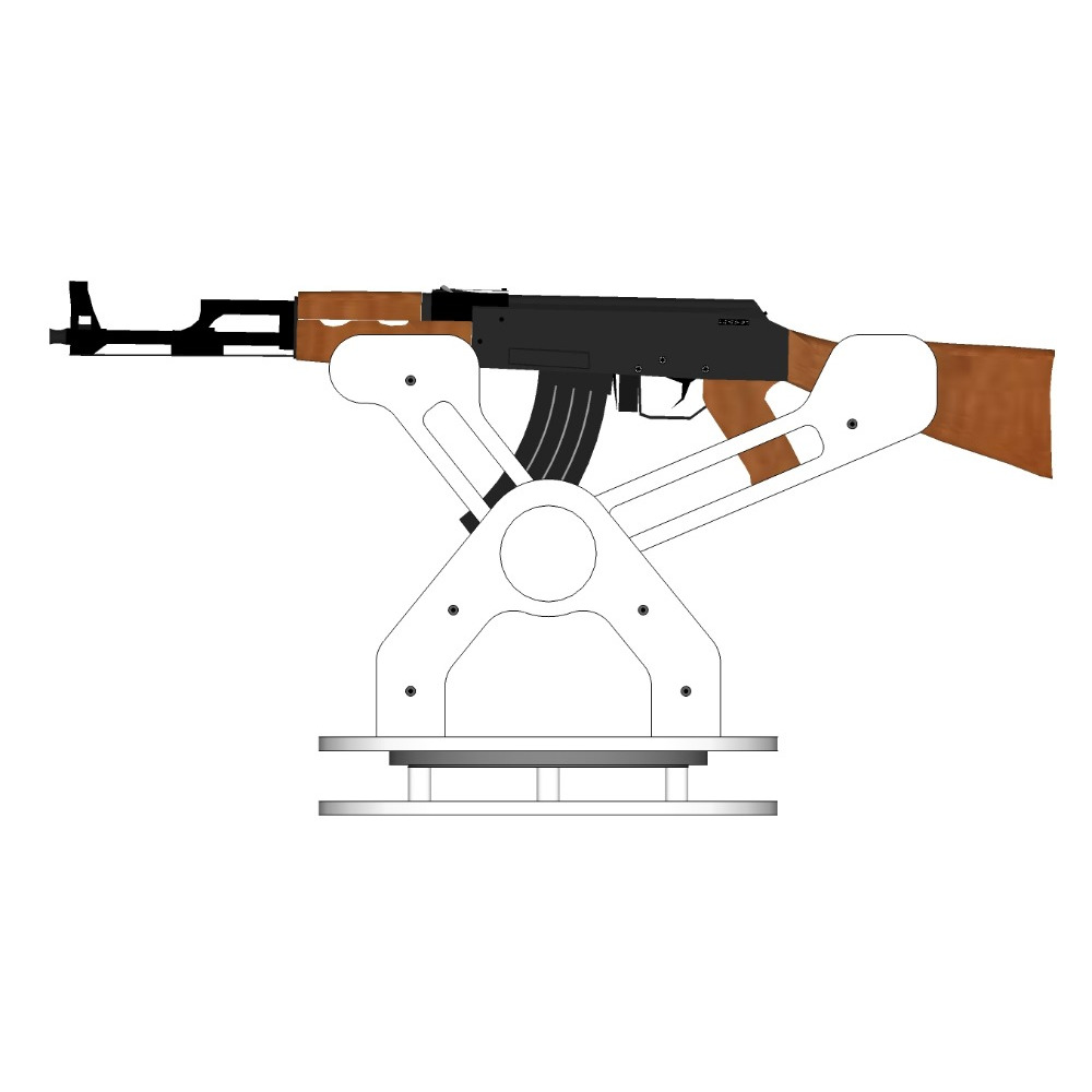
Designing the structure housing the rifle in SketchUp
Structure housing the rifle under construction before the painting

Structure housing the rifle under construction before the painting
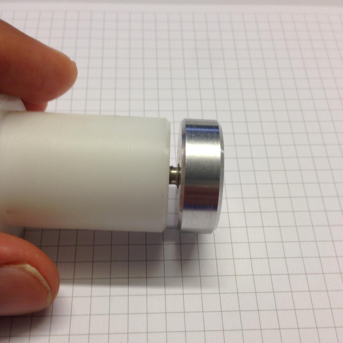
Main shaft in nylon with the trimmable housing for the permanent magnet.

Main shaft in nylon with the trimmable housing for the permanent magnet.
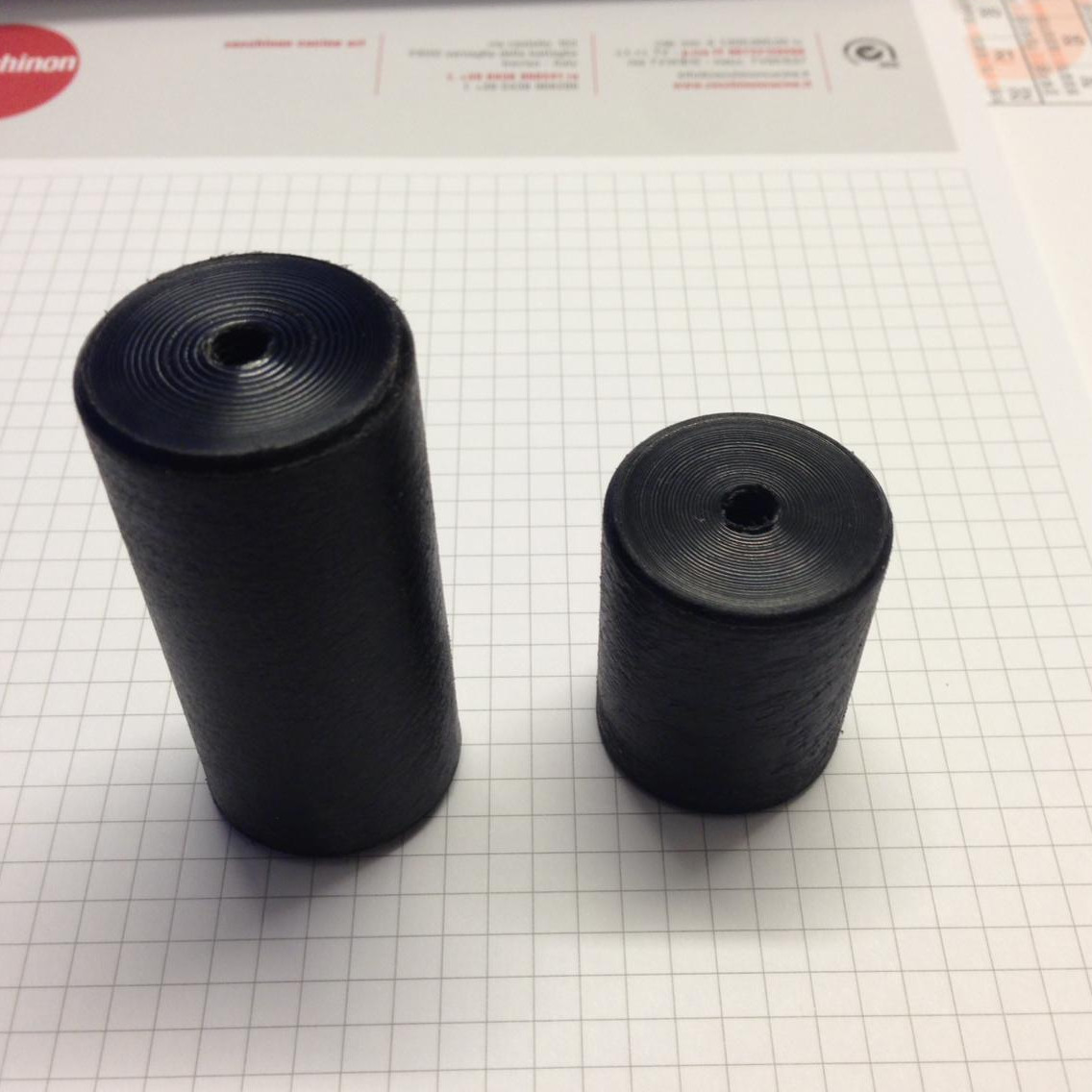
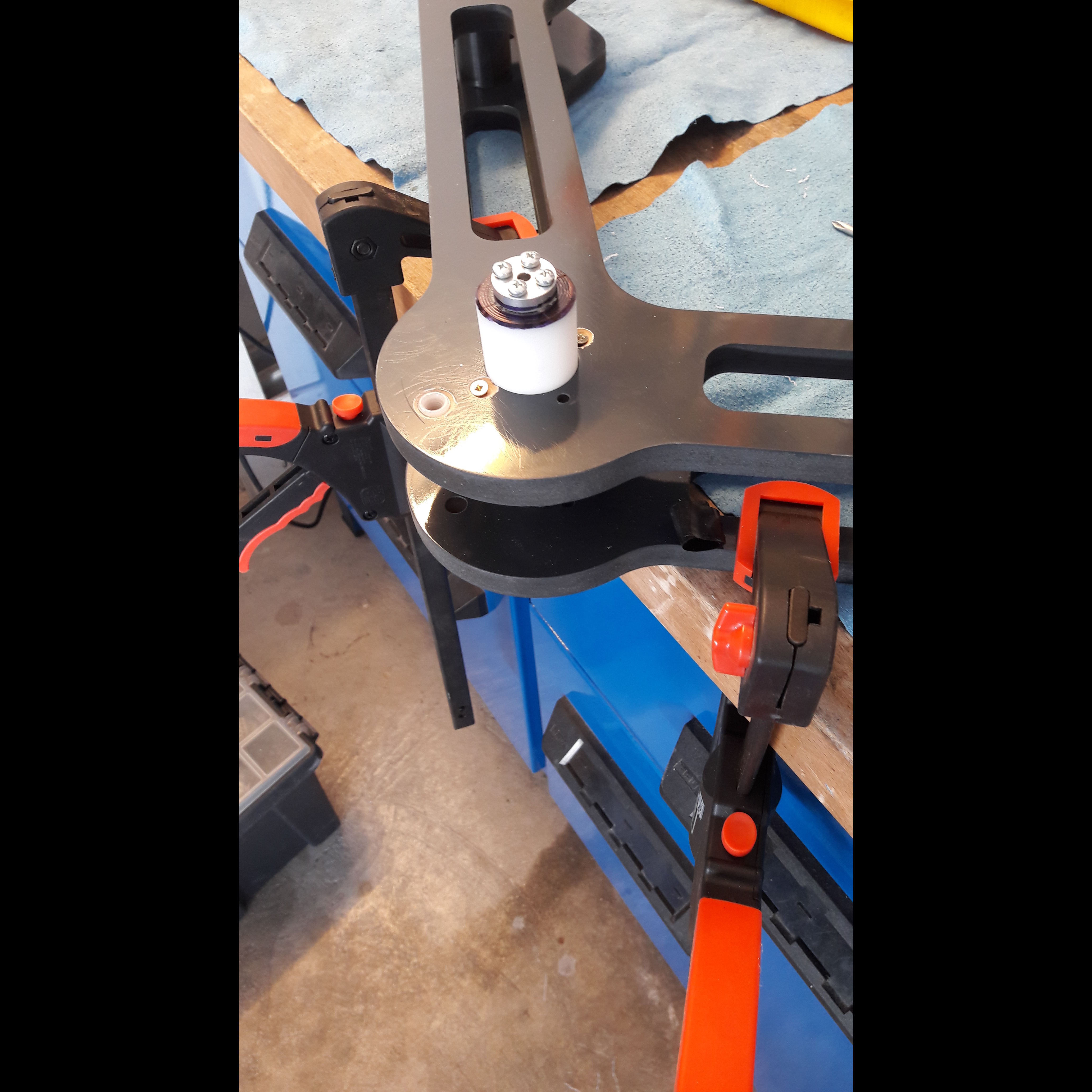
Nylon spacers used to tighten the structure. Designed and machined using a lathe.
Detail of the CNC milled base-plate where the other hall sensor is placed.
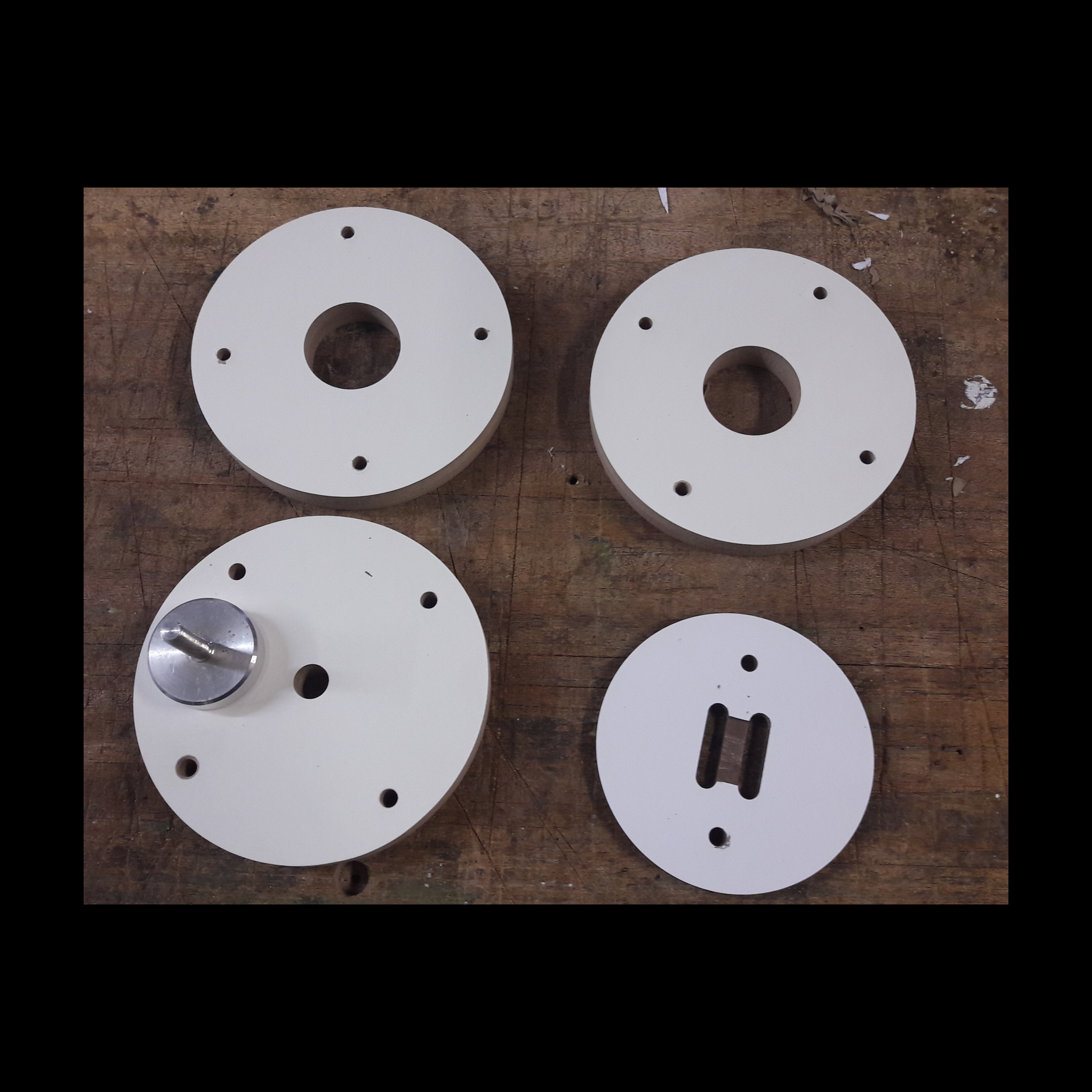
Other MDF particulars of the structre, and the aluminium housing for the other permanent magnet.

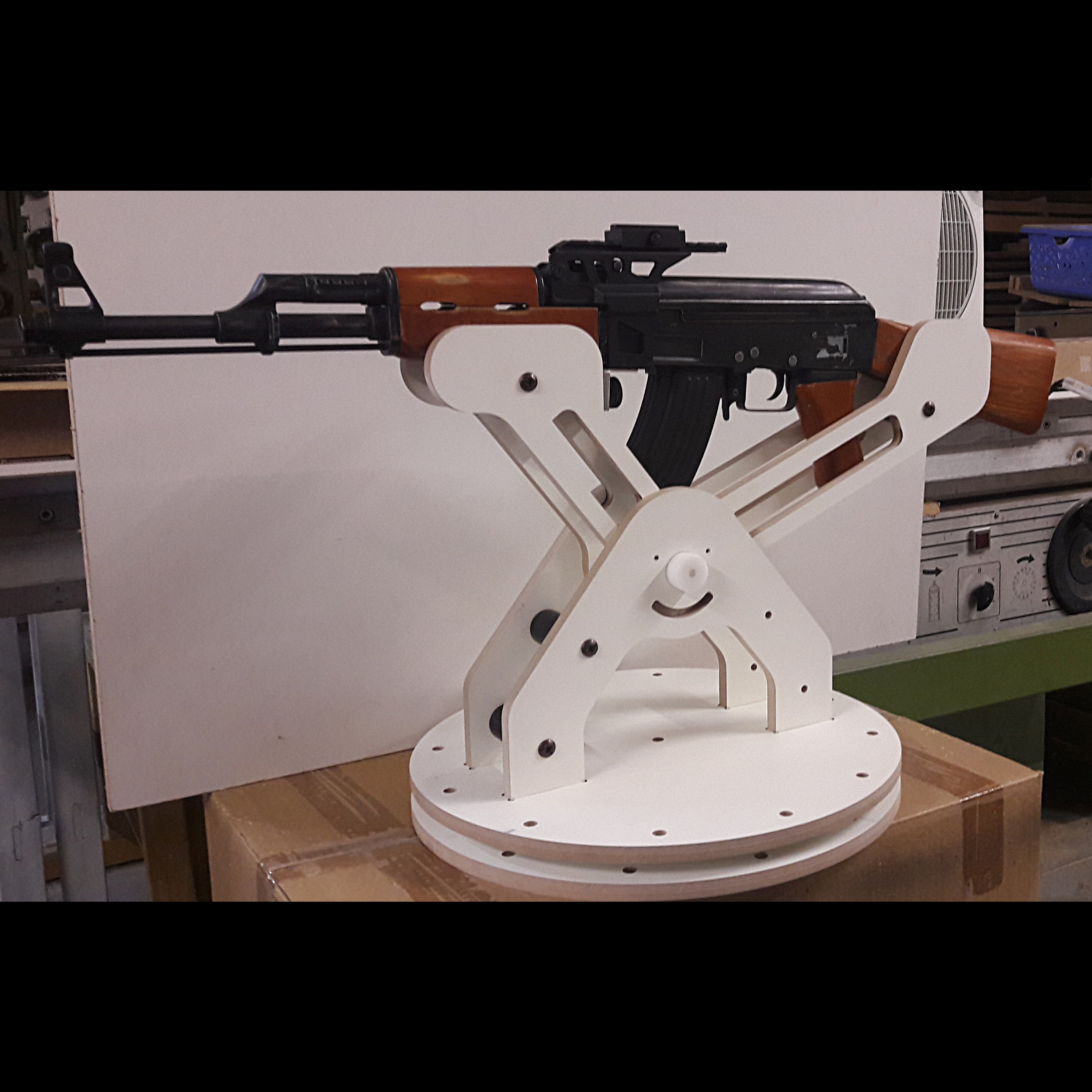
Structure housing the rifle under construction after the painting.
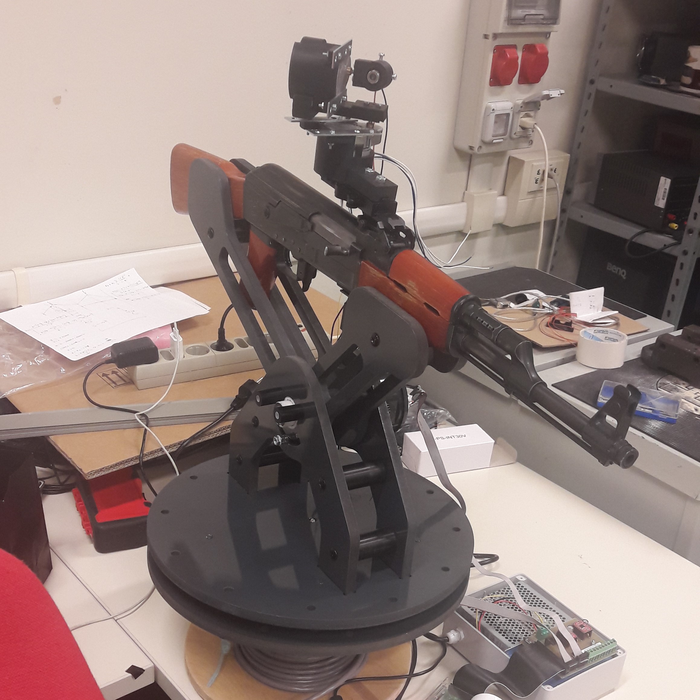
The mounted on the rifle structure with the motors and the laser projector.
Angular sensors calibration: On the main nylon shaft has been bolted an aluminium servomotor hub, in order to join shaft and motor.

Angular sensors calibration: calibration marks printed over the main shaft. These have been used to perform the calibration and harmonic compensation of the angular Hall effect sensor.

Angular sensors calibration: one of the stepper motors used as laser projector actuators has been mounted on the structure. Motor has been bolted over to appositely realized nylon supports, and fixed to the main shaft by means of the hub. Stepper motor is now ready to drive the main shaft, and perform the necessary calibration of the angular hall encoder.

Angular sensors calibration: rifle housing structure deprived of the two supporting arms, to guarantee the 360° rotation necessary for the calibration procedure.
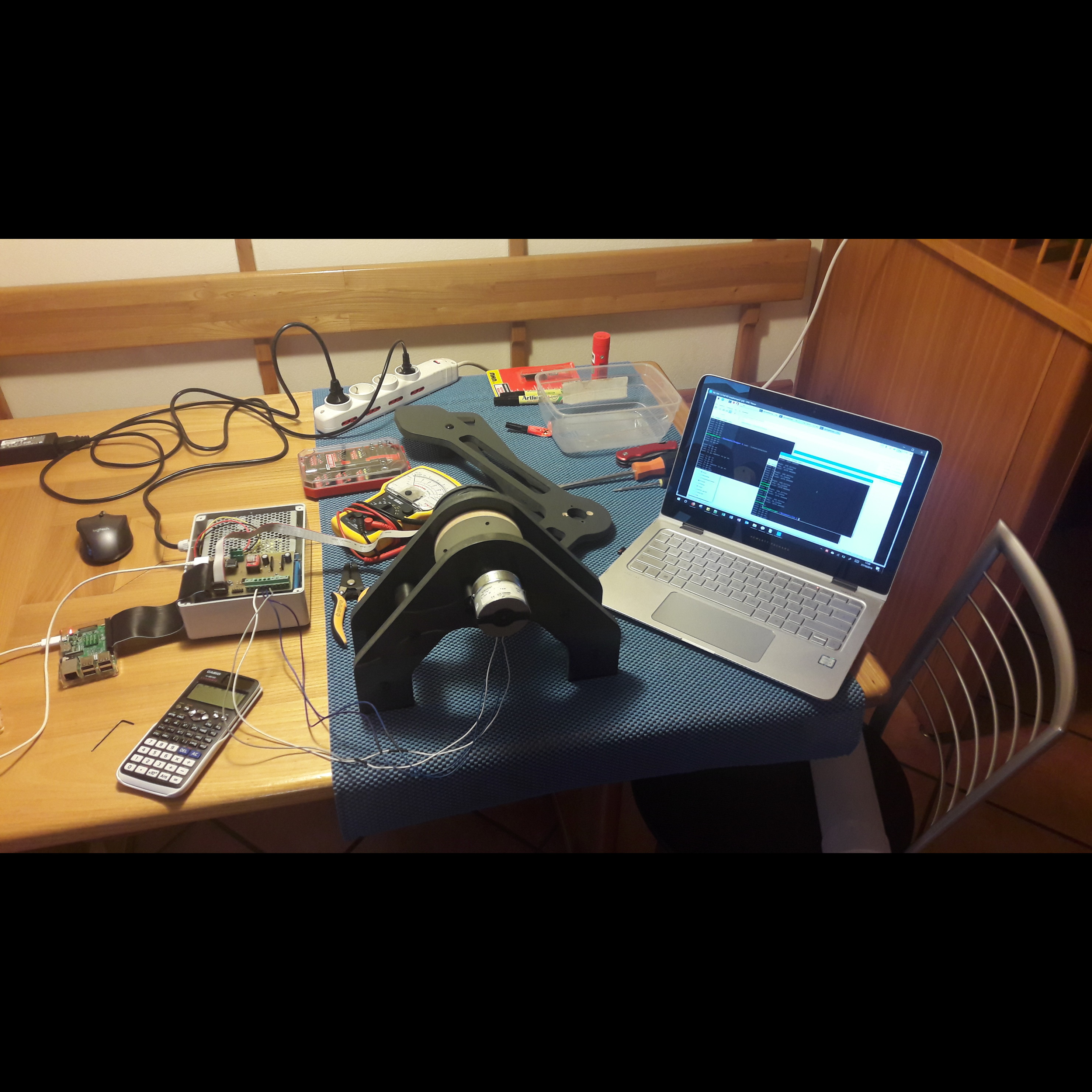
Automatic calibration procedure of the angular Hall effect sensors. PC is interfaced with the RPi, and the latter to the main PCB we have realized.
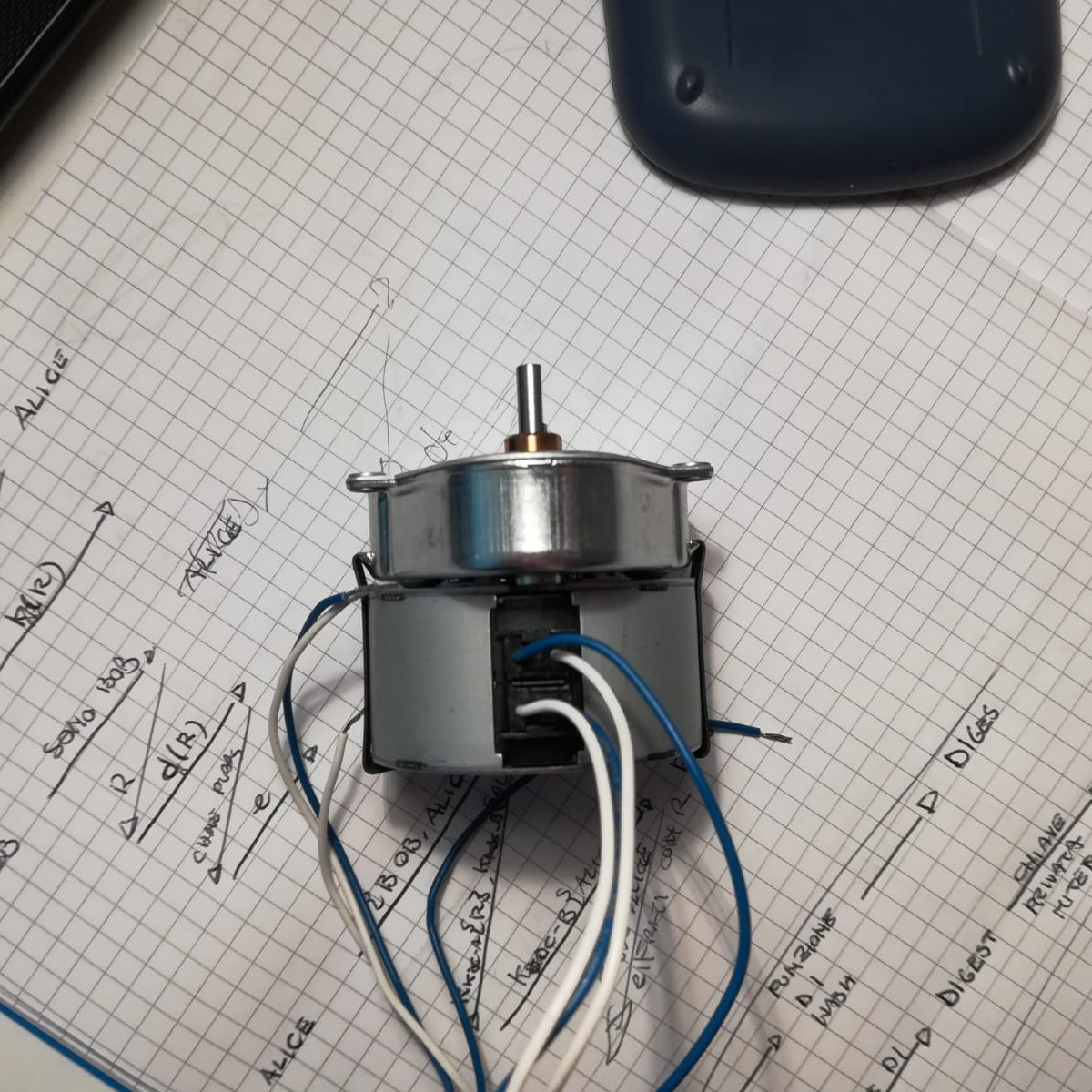
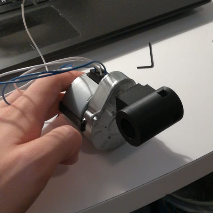
One of the Crouzet-motors steppers and the relative gearbox.
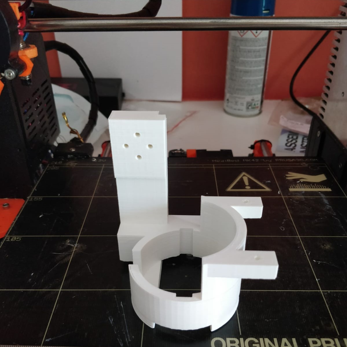
The 3D printed structure for the motors.

The 3D printed structure for the motors.
Motor with mounted the printed support for laser projector.

The mounted structure with the motors and the laser projector. Print has been fixed over an adapter compatible with standard picatinny rail.

Particular of the laser pointer inserted into the printed support. Note the micrometric regulation mechanism.
3D view of the PCB for the power supply and the input/output intefaces from the rifle side.
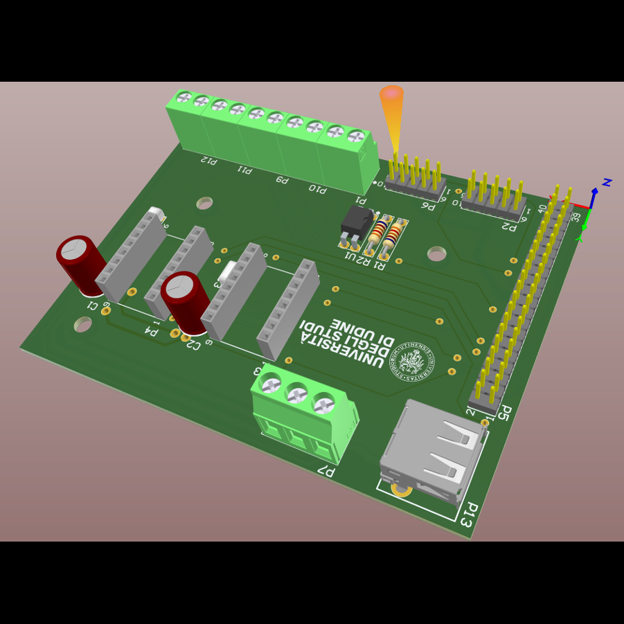
3D view of the PCB for the power supply and the input/output intefaces from the rifle side.
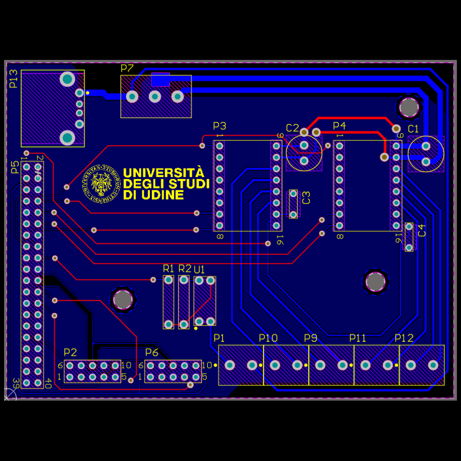
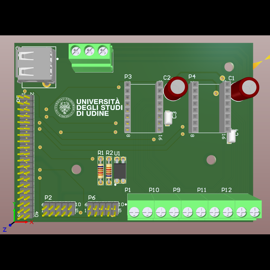
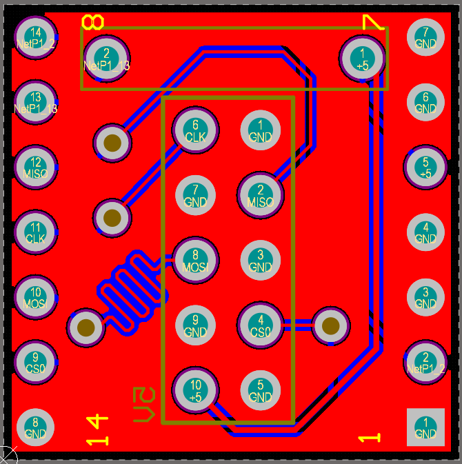
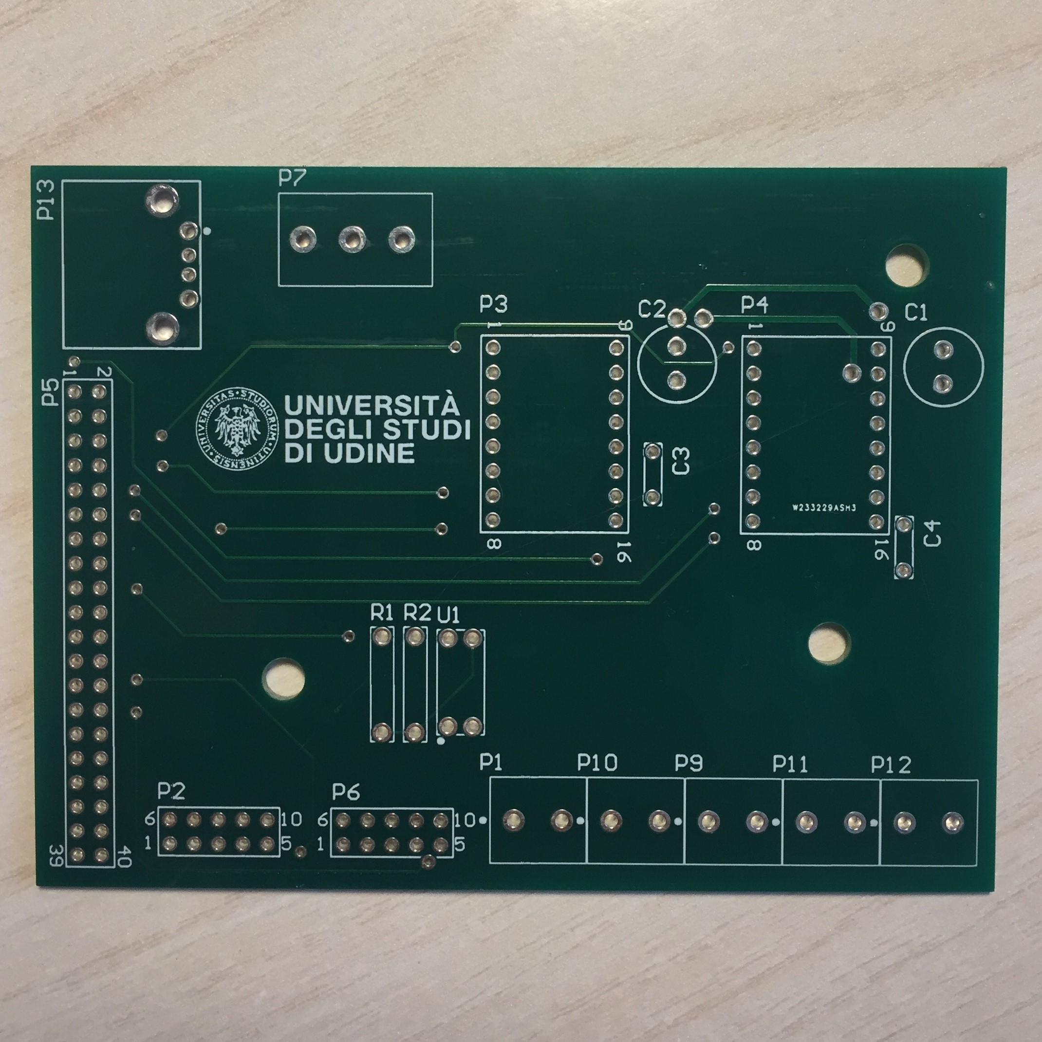
A 2D view of the PCB without the components. Here it's possible to see all the interconnections. The P7 slot is for the power supply. The P13 is for the supply of the RPi. On P4 and P5 there are the A4988 drivers. On P2 and P6 the pins for the sensors. On P5 the pins for the RPi. On P1, P10, P9, P11 and P12 the supply for the two sensors and the steppers.
A 3D viev of the PCB for the angular sensors.
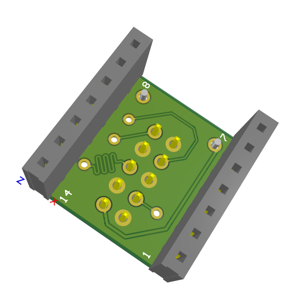
A 3D viev of the PCB for the angular sensors.
A 2D viev of the PCB for the angular sensors (BOTTOM).
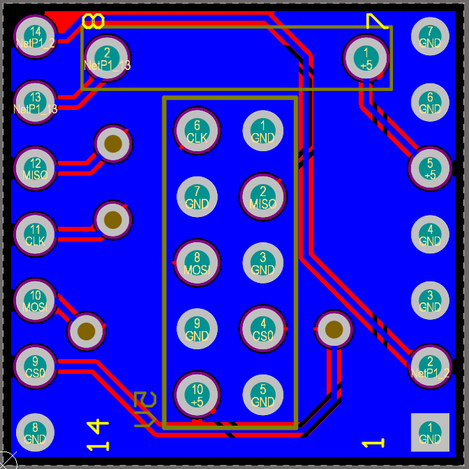
A 2D viev of the PCB for the angular sensors (TOP).
Before PCB realization: some tests on a breadboard, during the angular sensor firmware writing.
Before PCB realization: first tests regarding EMC immunity.
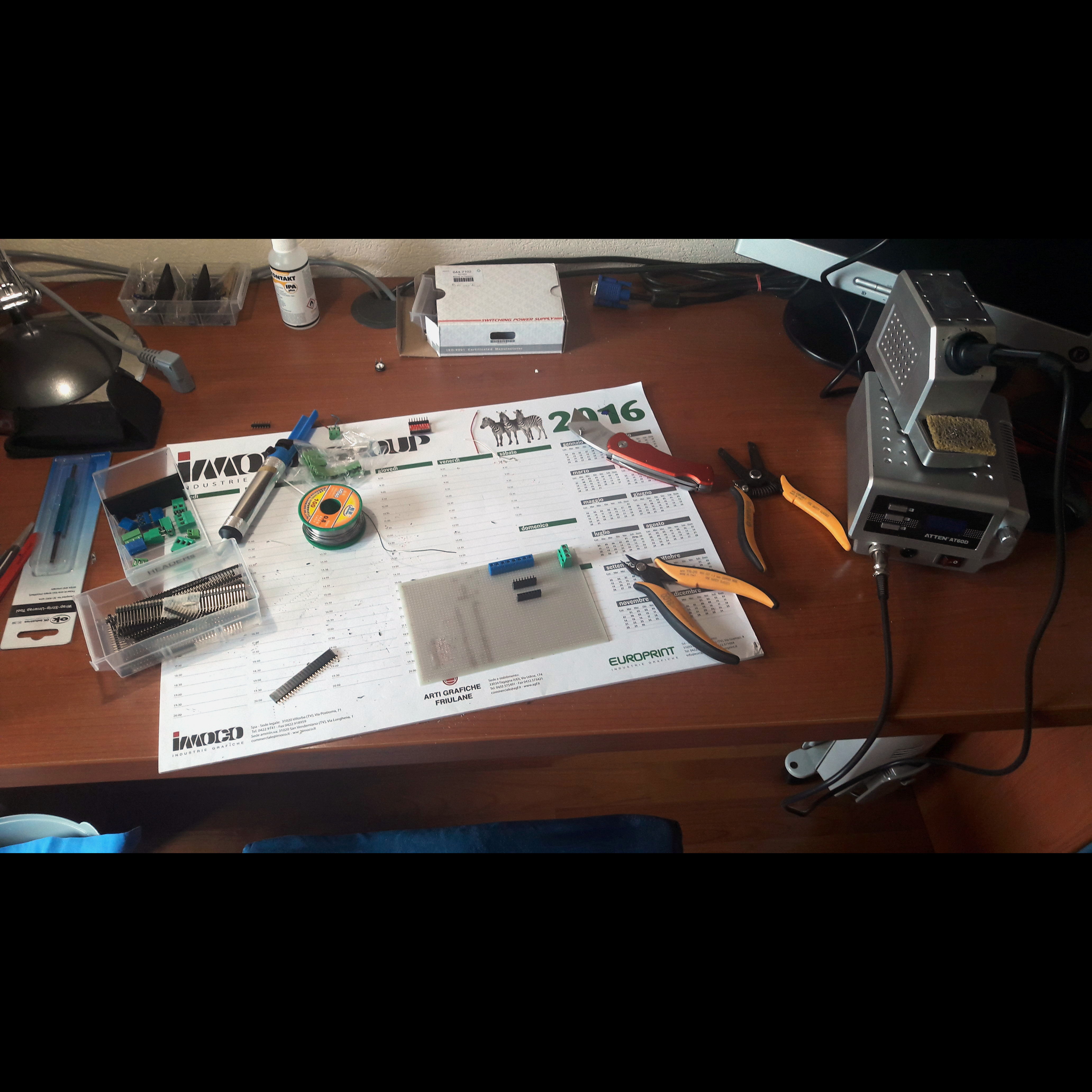
Before PCB realization: Making of the system mainboard on a perfboard, with the defininive design.
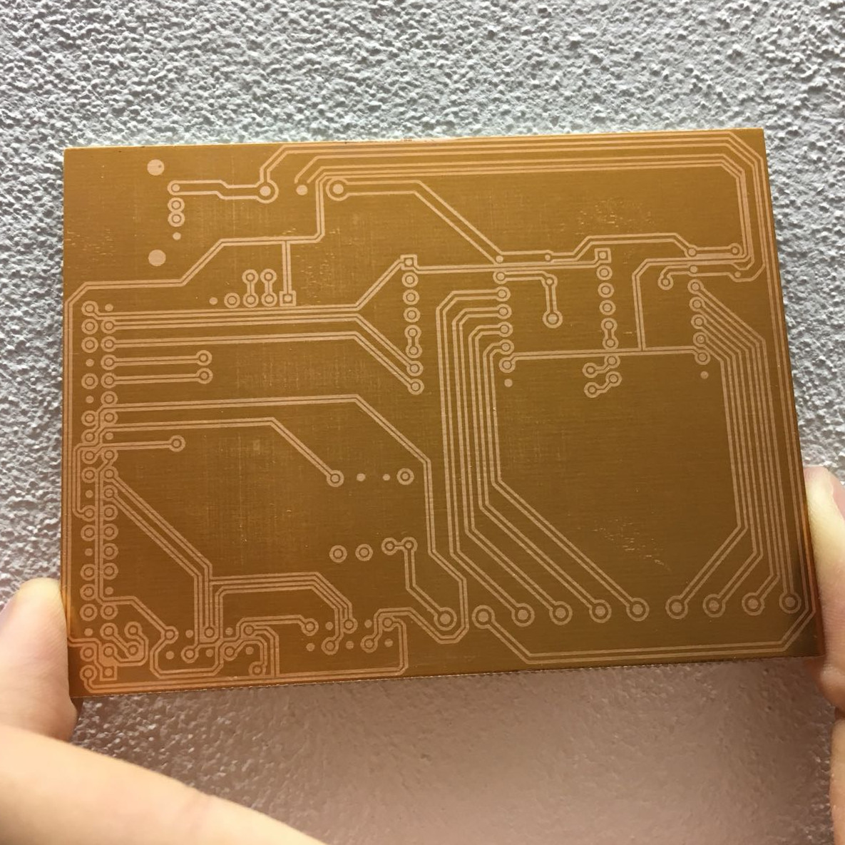
The first home made PCB for the power supply and the input/output intefaces from the rifle side. This picture is taken after the UV exposition, before etching. Etching phase is reported in the main page of this site.
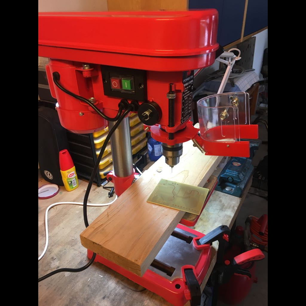
Making the drills and vias by hand, using a drill press.

PCB after drilling. Now components are ready to be soldered.
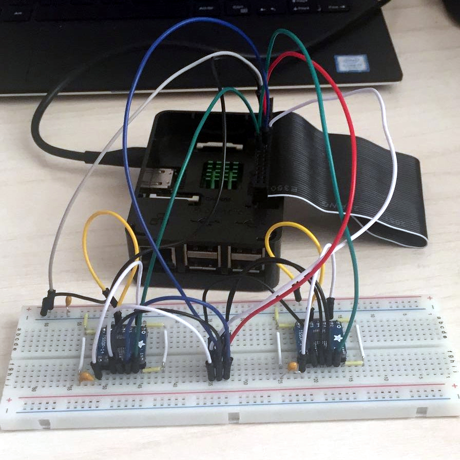
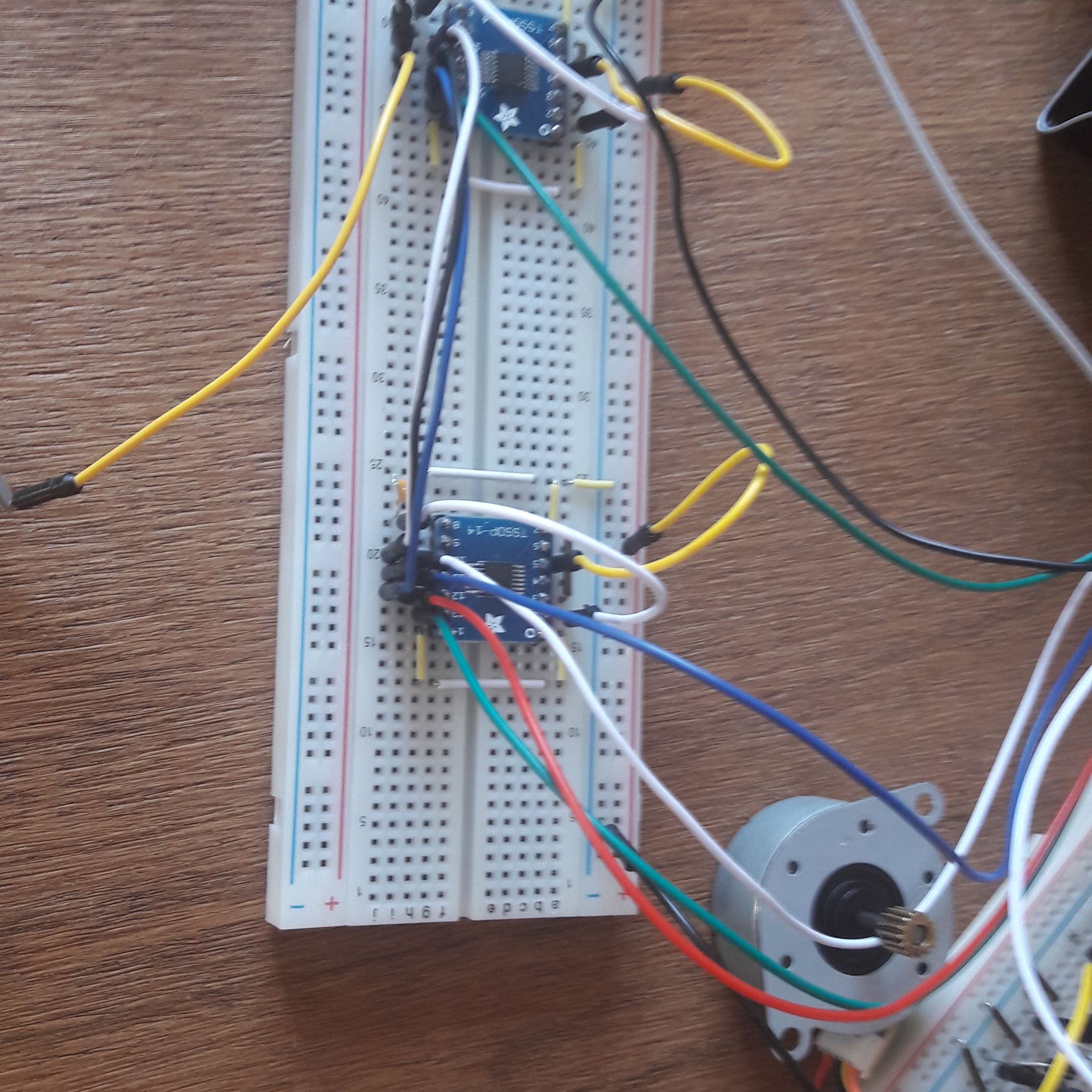
The home made PCB or the power supply and the input/output intefaces from the rifle side with the components and connected to the power supply, the Raspberry Pi, the sensors, the motors and their drivers.
The home made PCB or the power supply and the input/output intefaces from the rifle side with the components and connected to the power supply, the Raspberry Pi, the sensors, the motors and their drivers.
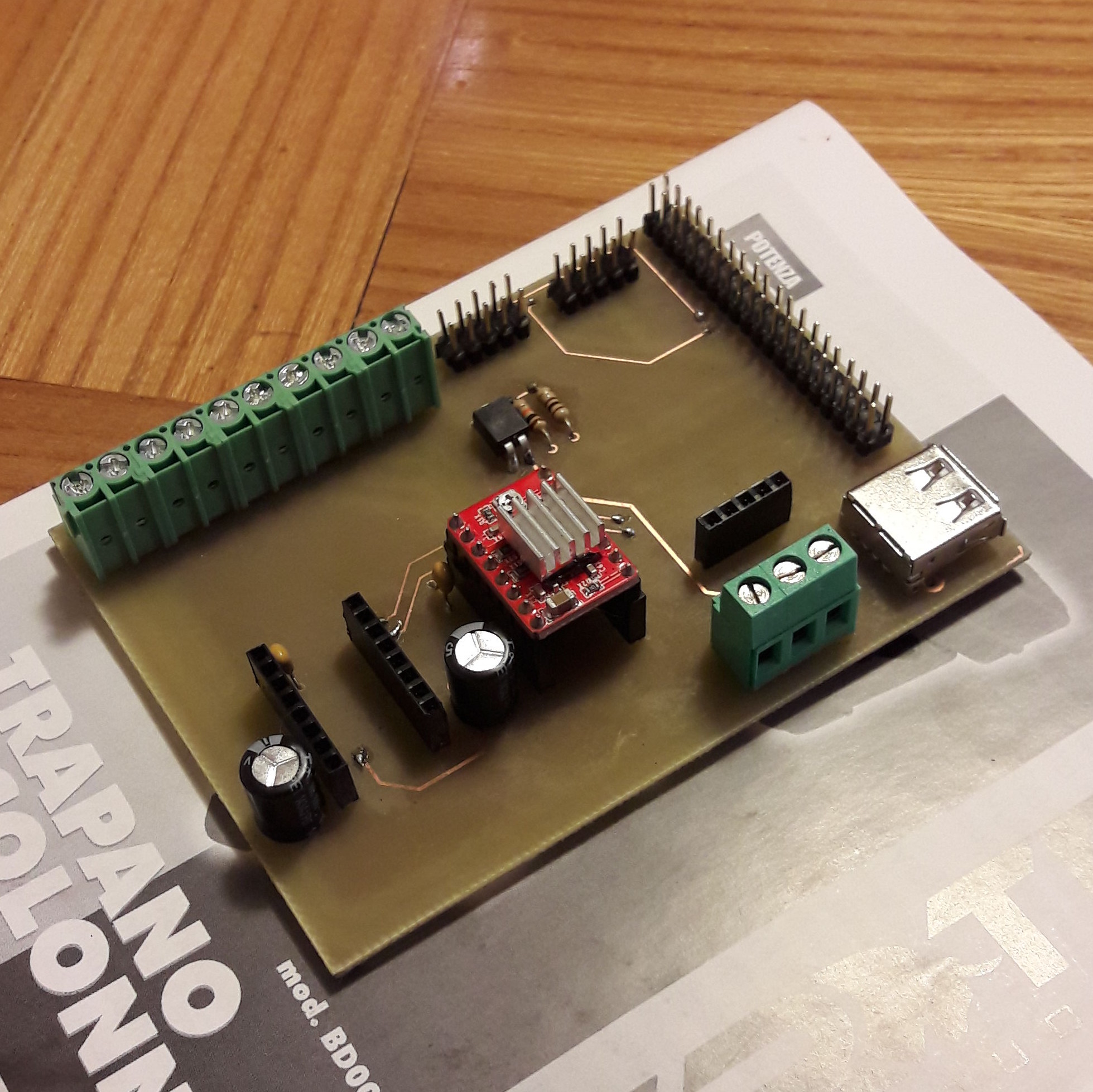
The definitive realized PCB or the power supply and the input/output intefaces from the rifle side.
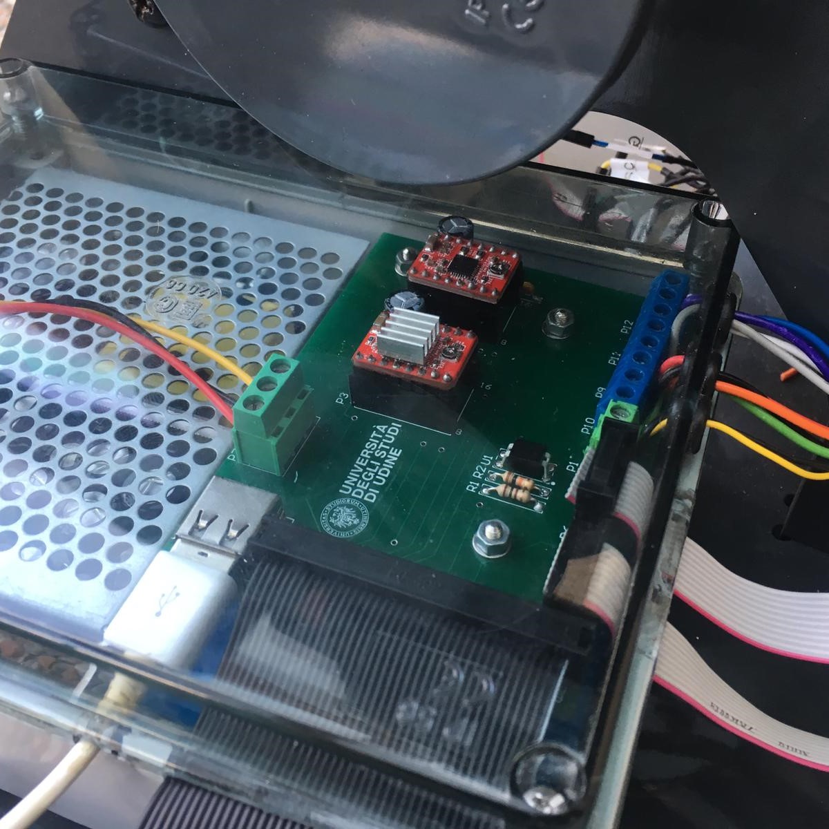
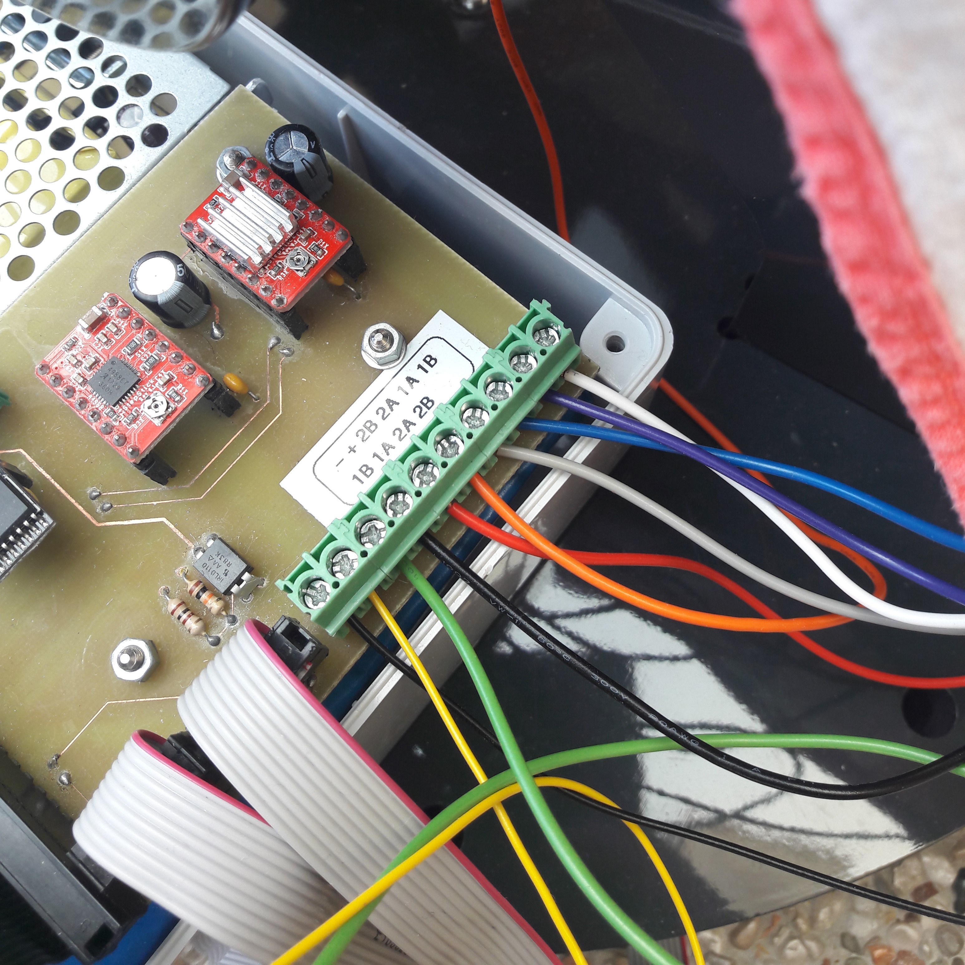
The definitive realized PCB or the power supply and the input/output intefaces from the rifle side with the components and connected to the power supply, the Raspberry Pi, the sensors, the motors and their drivers.
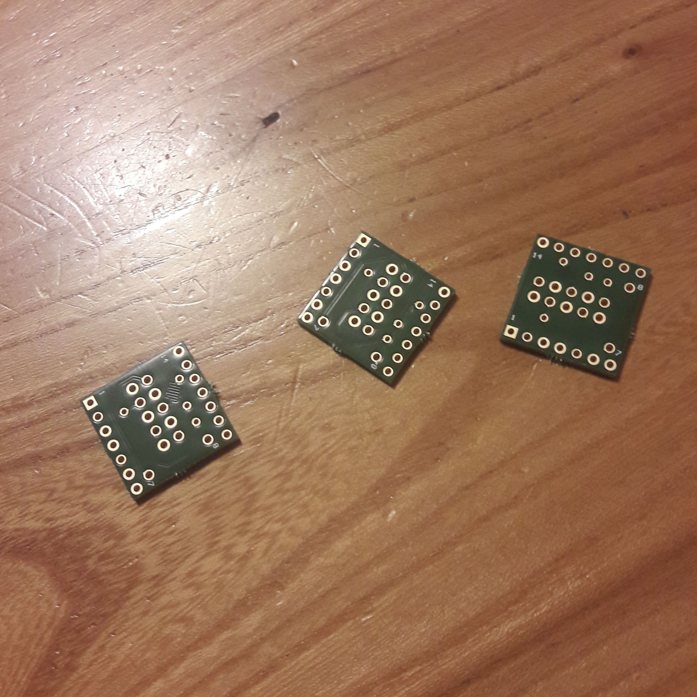
The definitive PCBs for the angular sensors.

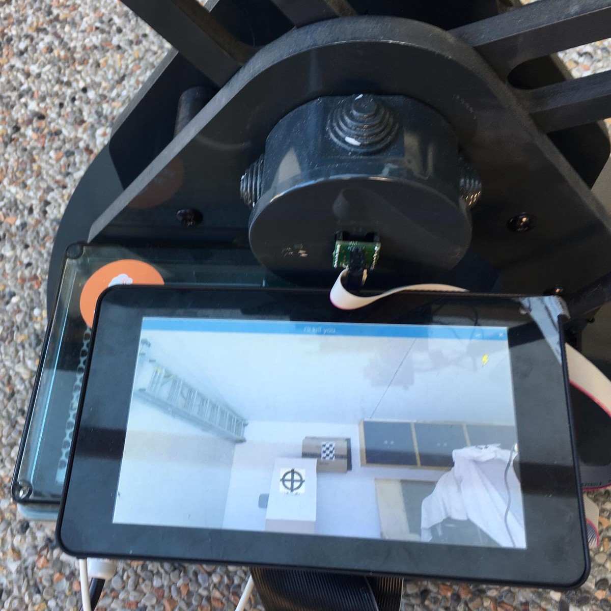
The angular sensor connected through the interfacing board with the Raspberry Pi. Flat cable has overabundant no. of poles, used to improve radiated immunity. You can see the sensor's PCB board. The sensor itself has been embedded into the watertight junction box.
The rifle structure and the two camera forming the RGB-D stereo setup.

The whole structure of the prototype. There is the box with the power supply and the PCB, the Raspberry Pi with its LCD screen, the structure to move the rifle and, at the top, the structure to move the laser with the two steppers.

"Analogic" aiming view.
"Digital" aiming view.

Aim assistance in action.
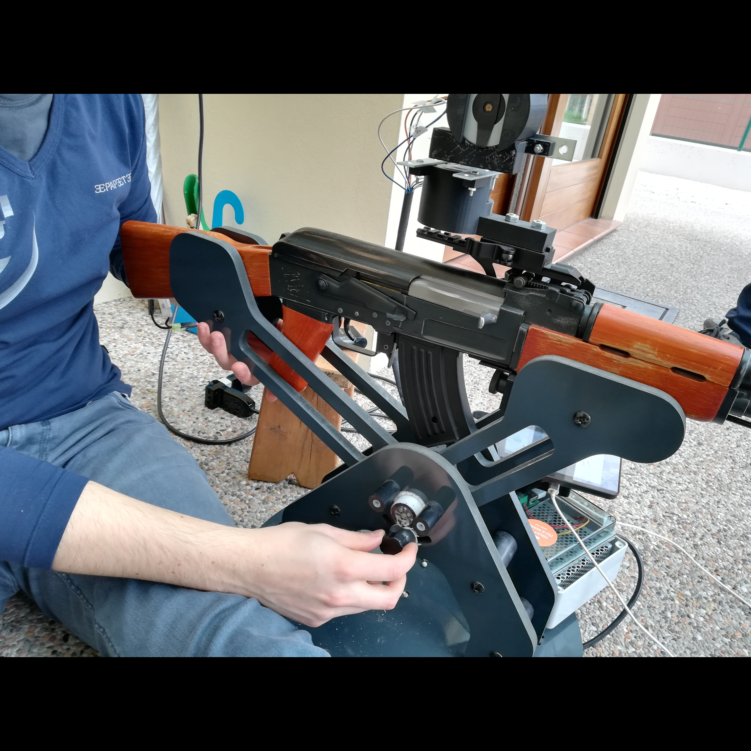
Particular of the rifle, where it is visible the picatinny rail where the projector's structure is mounted. It is also visible the knob used to fix the rifle in position.
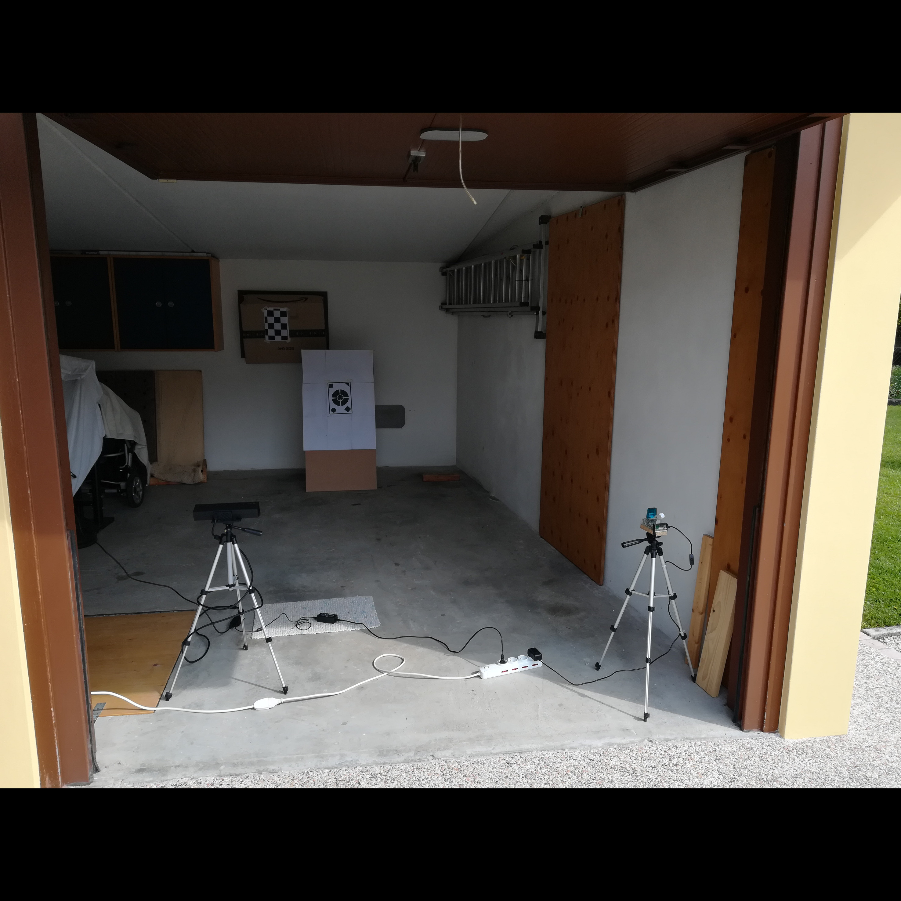
The two camera forming the RGB-D stereo setup, near the target.
Trajectory made by the laser projector. Points are the correspondent spots in the virtual image plane of the projector.
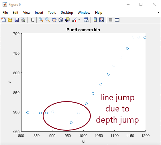
Points extracted by the spot detection algorithm, by one of the heads (Kinect) of the stereo camera.
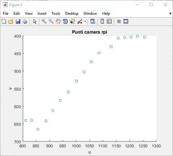
Points extracted by the spot detection algorithm, by one of the heads (RPi camera) of the stereo camera.
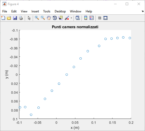
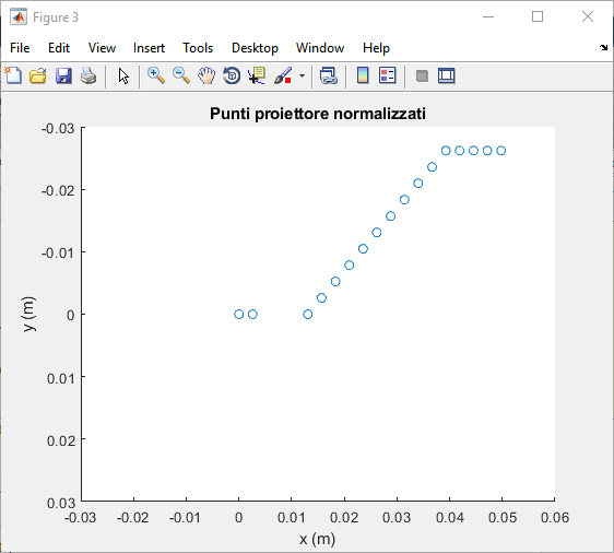
Same points extracted by the spot detection algorithm, but normalized by means of the RPi camera's intrinsic parameters.
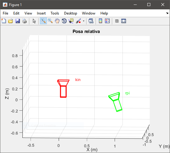
Estimated relative pose (modulo the translation magnitude) between the two heads of the stereo camera.
Actual pose of the two cameras forming the RGB-D stereo setup, near the target.

Estimated relative pose (modulo the translation magnitude) between one of the two cameras and the laser projector.